Siemens NX MCD: Simple Robotic Arm Modelling
In this module you will model a simple robotic arm mechanism using Siemens NX.
What you need
Software
Siemens NX version 1872 or newer (pre-installed on the lab PC)
Files
CAD files of the examples used in this module can be found here: https://fh-aachen.sciebo.de/s/AFAGrOi2zRFL1y7
For this task, the correct assembly can be found in simple_robotic_arm. Download all the parts from the simple_robotic_arm file and open ASSEMBLY_simple_robotic_arm in Siemens NX.
Preparation
Assignment
In this exercise a running simulation of a simple robotic arm mechanism will be created. The CAD files are available. In Siemens NX MCD, different physical properties will be assigned to parts in order to reflect the function of the simple station.
Note
When you first start NX, you may get an error saying there are no licenses available. Click “OK” and navigate to File->Utilities->Select Bundles. In the window that opens, select and add both available bundles then click OK. This solves the error.
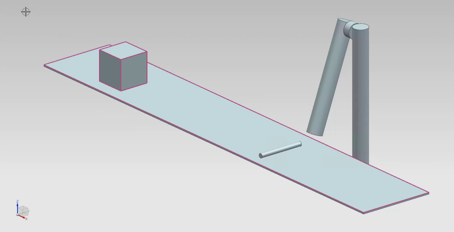
Fig. 1 Simple robotic arm functionality
Box and Conveyor Band
In the first steps, rigid and collision bodies will be assigned to parts the will interact with each other.
Todo
Assign a rigid body to the box and call it
Box.Assign a collision body to the box and call it
Box. Hint: to choose the entire box volume, right click on the box and selectChoose from list. Then select the entire box from the list.Assign collision body to the upper surface of the transporter band and call it
Transport_band.Assign a transport surface to the upper surface of the transporter band and call it
Transport_band. Specify the correct direction vector and set the parallel velocity to100 mm/s.Run the simulation and check if the box is transported on the transport band.
Simple Robotic Arm
Todo
Assign a rigid body to the robotic arm and call it
Robot_arm.Assign a collision body to the robotic arm and call it
Robot_arm.Assign a hinge joint to the robotic arm and call it “Robot_arm_HingeJoint”. Specify the direction vector and the anchor point in a way that it rotates around the robotic joint.
Assign a position control to the hinge joint object. Test different
DestinationandSpeedsettings.Finally set the destination to
0and the speed to500 °/s
Collision Sensor
Todo
Assign a collision sensor to the small cylinder on the transport band and give it a suitable name.
Conditions - Using Operations as if-Statements
Todo
Create an operation in the
Sequence Editor. Choose the position control object as theSelect Objectchoice. Make a check next topositionand give in a value of70. Select the collision sensor object (from the ) as the condition object and specify thattriggered == true. Name the operationArm_out.Create a second operation. Choose the position control object as the
Select Objectchoice. Make a check next topositionand give in a value of0. Select the collision sensor object (from thePhysics Navigator) as the condition object and specify thattriggered == false. Name the operationArm_in.
Run the simulation and check if it achieves the desired behavior.