PLC-Basics
Programmable Logic Controllers (PLC) are computers which are commonly used in commercial and industrial control applications. Generally speaking, PLCs monitor inputs and other variable values, make decisions based on a stored program and control outputs to automate a process or machine.
A PLC typically consists of input and output modules, a Central Processing Unit (CPU) and a programming device. The primary function of the input unit is to convert the signals at the inputs into logic signals which can be used by the CPU. The CPU analyzes the status of inputs, outputs and other variables and executes the stored program. After that, the CPU changes the output signals.
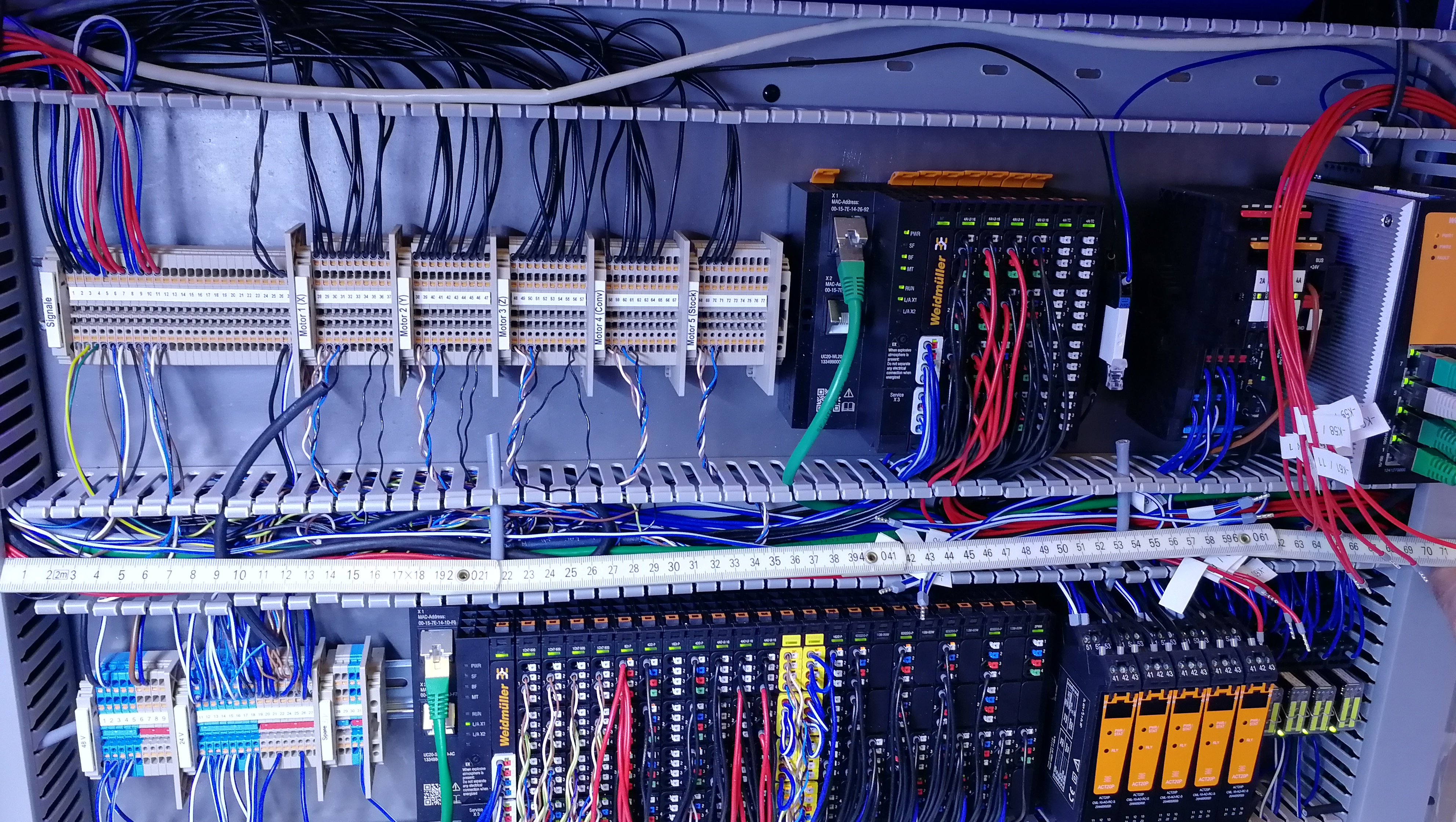
Fig. 24 Example for PLC wiring for industrial applications
Advantages in contrast to hard-wired control:
Easy to modify input and output devices
High flexibility due to modular design
Significant reduction of cabling
Solid-state, no moving parts
Smaller physical size
Integrated diagnostics and override functions
Easy and cost-effective duplication possible
Communication capabilities
Information processing
Information at the inputs of the PLC are processed in cycles. First, the CPU queries the input channels and stores the data in the working memory. This storage area is called “input image” as the stored input data does not show the current state of the inputs but the available data at the time of sampling.
Next, the program is executed step by step and the variables are stored in the memory. Finally, the calculated output parameters are stored in the “output image” and transferred to the output channels to control the connected machine.
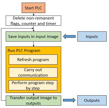
Fig. 25 Cyclic information processing of PLCs
Types of input and output signals:
Binary inputs: Input module can distinguish between a high and a low level of the input signal (typical value: 0V and 24V).
Binary outputs: Output modules generate TRUE (5V) or FALSE (0V) values which are typically intensified (24V) using transistors or relays.
Analog inputs: A physical measurand is transformed into a voltage or current signal using a transducer. The resulting signal is transferred to the analog inputs of the PLC.
Analog outputs: A voltage or current signal is generated to control actuators.
PLC Programming (IEC 61131)
PLC programming is standardized in the IEC 61131.
Controller configuration and resources
Creating a controller configuration, the hardware structure is specified in the programming environment. All resources which are controlled by the PLC software (input, output modules, interface cards, etc.) are declared. Nowadays, this is usually done automatically by scanning the connected components or by drag-and- dropping the parts.
Input channels are declared using %I and outputs specified writing %Q.
The following letter defines the data type of the signal (bit X, byte B, word W,
doubleword D). In this context, the declaration %IX1.2 calls the second channel
of the first binary input card.
Labelling of input and output addressing |
|
|
Example |
|||||||
AT% |
I Input |
x Bit |
AT%IX1.2 |
|||||||
Q Output |
B Byte, 8 Bit |
AT%QB0 |
||||||||
W Word, 16 Bit |
AT%QW7 |
|||||||||
D Doubleword, 32 Bit |
AT%QD5 |
|||||||||
Tasks
Tasks organize the time schedule of programs. It works a bit like a cyclic step counter, which selects the instructions of the program in a clock-controlled way. Based on that, the CPU processes the instruction which is stored in the selected storage area.
Several programs can be assigned to one task running all in the same cycle time. The following process is conducted (IPO principle; input-processing-output):
Read input data of all programs.
Processing of all programs.
Output of the output data of all programs.
The cycle time of all programs assigned to one task is identical as the output data of all programs is transferred simultaneously at the end of the processing cycle.
One CPU can process multiple tasks with different cycle times (multitasking). Therefore, the computing power is distributed between the different tasks using interrupt signals for changing.
Program Organization Units (POUs)
An object of the type POU is a Program Organization Unit in a CODESYS project.
You write source code for the controller program in POUs. There are the
following types of POUs:
Programs
Function Codes
FCFunction Blocks
FB
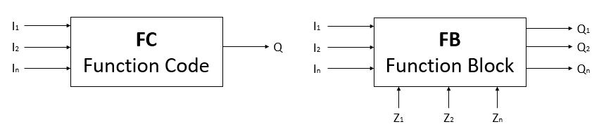
Fig. 26 Difference between Function Codes and Function Blocks
Function Codes can have several input variables but only one output variable. This variable is the return value of the Function Code. Function codes have no internal memory, thus they cannot store intermediate values. Function Codes can be separated between standard and user-specific functions. Standard functions like for example AND, ADD or BYTE_TO_WORD can be used directly during programming without declaring it separately.
Function Blocks can also be standardized or user-specific. Examples for
pre-defined FBs are triggers, counters and timers. FBs can store intermediate
values for the next IPO cycle and can have several outputs Q. The output signals
are created by connecting the inputs I and the states Z.
Variables
Variables are used to establish a communication between different program organization units. Different kinds of variables are available:
VAR: Local variables which are only valid in the associated POU.VAR_GLOBAL: Global variables are valid in all POUs. They are used for communication between different programs.VAR_INPUT: Input variables which are used to write inputs in FCs or FBs.VAR_OUTPUT: Output variables of FCs or FBs.VAR_IN_OUT: Input and output variables can be changed in the FB and then be released.VAR_RETAIN: Variables retain the value when the PLC is put off and on again.VAR_PERSISTENT: Variables retain the value if the software is loaded on the PLC.
Standard data types:
Datatype |
Size |
Range |
Example |
|
Bit sequence |
BOOL |
1 Bit |
FALSE / TRUE |
FALSE |
BYTE |
8 Bit |
16#00 … 16#FF |
16#00 |
|
WORD |
16 Bit |
16#0000 … 16#FFFF |
16#0000 |
|
DWORD |
32 Bit |
16#00000000 … 16#FFFFFFFF |
16#00000000 |
|
Whole numbers |
SINT |
8 Bit |
-128 … 127 |
0 |
INT |
16 Bit |
-32768 … 32767 |
0 |
|
DINT |
32 Bit |
-2147483648 … 2147483647 |
0 |
|
Whole numbers without sign |
USINT |
8 Bit |
0 … 255 |
0 |
UINT |
16 Bit |
0 … 65535 |
0 |
|
UDINT |
32 Bit |
0 … 4294967295 |
0 |
|
Floating point figure |
REAL |
32 Bit |
-3.4 * 10^38 … 3.4 * 10^38 |
0 |
Time |
TIME |
|||
Time of day |
TIME_OF_DAY |
|||
Date |
DATE |
|||
Character sequence |
STRING |
A typical variable declaration consists of five parts:
<variable name> AT<address> :<data type> :=<initial value>; (* comment *)
example: buttonStart AT%IX0.0 :BOOL :=FALSE; (*Start Button*)
Note
It is helpful to use speaking names instead of numbers to make it easy to understand the program (e.g. buttonLight and buttonVentilator instead of button1 and button2).
Derived data types:
Standard data types can be modified to fulfil special needs:
TYPE Name : ... END_TYPE
Four different kinds can be distinguished:
Enumeration:
TYPE A_STATUS : (START,RUN,WAIT,STOP); END_TYPEArea:
TYPE A_DATA : UNIT(0..16#3FF); END_TYPEField:
TYPE A_4IN : ARRAY[1..4] OF A_DATA; END_TYPEStructure:
TYPE str_Motor : STRUCT ... END_STRUCT; END_TYPE
Enumerations are typically used if different options are possible and if easy readable code should be produced.
Programming languages (IEC 61131)
Programmable Logic Controller (PLC) programming as other programming tasks has defined set of rules described in the IEC 61131-3. In this Standard, information about programming concepts and industry accepted programming languages is provided. For this module, SCL, LAD and FBD are selected as they are most commonly used.
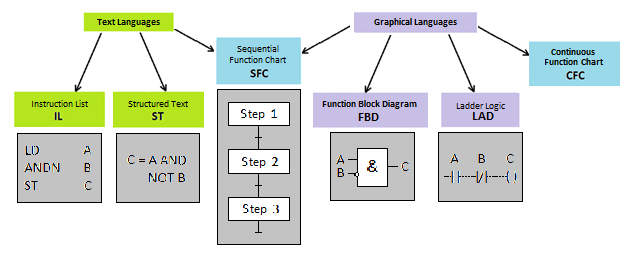
Fig. 27 Five programming languages of the IEC 61131-3 standard (source: https://www.motioncontroltips.com/iec-61131-3-plcopen/)
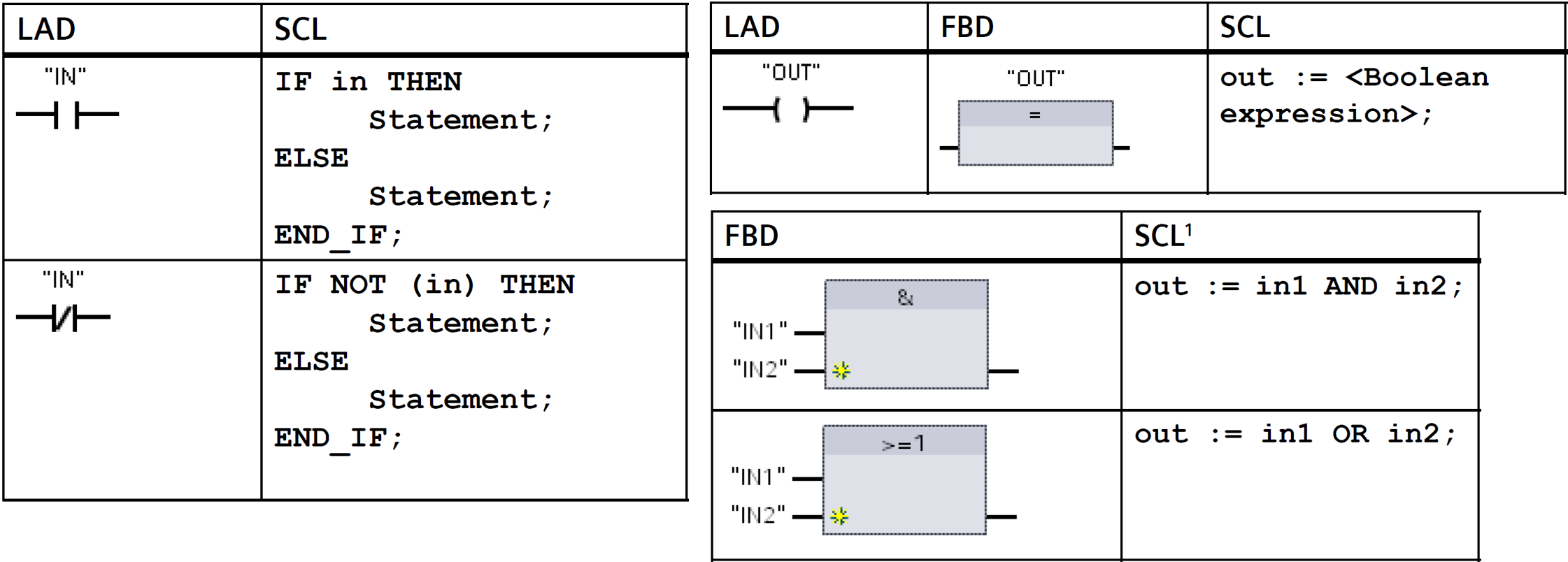
Fig. 28 SCL, LAD & FBD (ref: Siemens S7-1200 Programmable controller System Manual)
Structured Control Language (SCL)
SCL (Structured Control Language) is a high-level text-based programming language. It is based on PASCAL.

Fig. 29 An example of a SCL code 1.
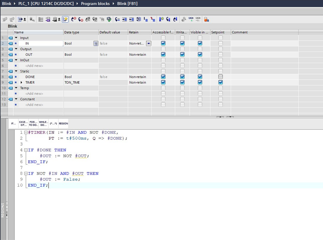
Fig. 30 An example of a SCL code 2.
Various important syntax for SCL are provided below:
Assignments: A := 10; (The variable A is assigned the value 10.)
Statements: blink : BOOL; (Create a variable blink and assign the type BOOL.)
Mathematical functions: +, -, *, /
Addressing of global variables (tags): “<tag name>” (Tag name or data block name enclosed in double quotes)
Addressing of local variables: #<variable name> (Variable name preceded by “#” symbol)
- Comments
Single line comment:
// commentMulti line comment and comments after end of ST line:
<statement>; (* comment *)
Operators: Standard operators in ST ordered after precedence:
Operation
Symbol
Precedence
Parentheses
(expr)Highest
Function Evaluation
MAX(A,B)Negation Complement
NOTExponentiation
**Multiply
*Divide
/Modulo
MODAdd
+Subtract
-Comparison
<,>,<=,>=Equality / Inequality
= / <>Boolean AND
& ANDBoolean Exclusive OR
XORBoolean OR
ORLowest
Note
A = B and A := B are NOT SAME!
= (equality operator) evaluates if the left and the right side is equal. If value of A is equal to value B. It returns TRUE if yes, else it returns FALSE.
:= denotes a statement. It is used for assigning value of right side to the left side. In this case, the value of B is assigned to A.
Combining operators:
IF (Input1) AND (Input2) OR (Input3) THEN
    Output1 := True;
END_IF
IF Statements: If statements are used for boolean queries.
IF [boolean expression] THEN
    <statement>;
ELSIF [boolean expression] THEN
    <statement>;
ELSE
    <statement>;
ENDIF;
CASE Statements: Case statements are one of the most important structuring methods to generate readable code. Case statements are typically used to program state machines.
TYPE
    Steps:(INIT:=0, START, RUN, END);
END _TYPE

VAR
    state: Steps; (*use of enumeration*)
END_VAR

CASE state OF
    INIT: Instruction_A;
    START: Instruction_B;
    RUN: Instruction_C;
    END: Instruction_D;
END_CASE
FOR Loops: It is used to repeat code a specific number of times.
FOR count := initial_value TO final_value BY increment DO
    <statement>;
END_FOR;
WHILE Loops: It is used to repeat the loop as long as some conditions are TRUE. A WHILE loop will repeat as long as a boolean expression evaluates to TRUE.
WHILE [boolean_expression] DO
    <statement>;
END_WHILE;
REPEAT Loops: It works the opposite way of the WHILE loop. This loop will stop repeating when a boolean expression is TRUE.
REPEAT
    <statement>;
UNTIL [boolean_expression]
END_REPEAT;
Ladder Diagram (LAD)
Ladder diagrams are specialized schematics commonly used to document industrial control logic systems.
In terms of TIA Portal program for Siemens PLCs, SCL plays an important role in programming of functions codes and function blocks. The Main [OB1] block is preferred to be programmed using the Ladder Diagrams.
A program written in LAD consists of networks. The language is based on relay logic. The flow of the logic ‘true’ across a network is similar to the flow of electricity across a relay logic. One can think of the left rail as being positive, and the right rail as being negative. The logic ‘true’ flows from the left rail to the right rail.
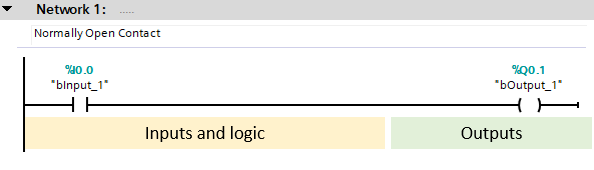
Fig. 31 An example of a network in LAD.
Various logical operations can be thus programmed in LAD. The following figure shows AND & OR logic after starting the PLC or simulated PLC.

Fig. 32 An example of logical operations in LAD.
A general list of Bit Logic instructions used in LAD are mentioned below
Operation
Symbol
Normally Open Contact (Address)
---| |---Normally Closed Contact (Address)
---| / |---Save RLO into BR Memory
---(SAVE)Bit Exclusive OR
XOROutput Coil
---( )Midline Output
---( # )---Invert Power Flow
---|NOT|---Insert branch
⮡Merge branch
⬏
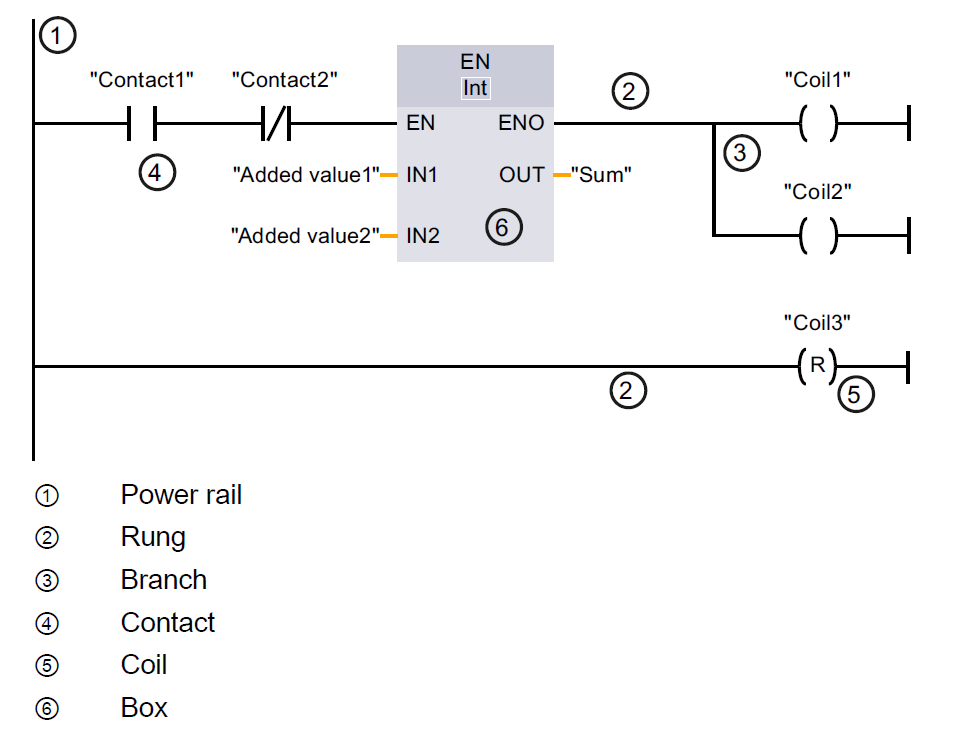
Fig. 33 An example of a network in LAD. (ref: SIEMENS TIA Portal STEP 7 Basic V10.5)
Function Block Diagram (FBD)
FBD is another graphical programming language. It uses Boolean algebra-based blocks to develop codes. A function block is depicted as a rectangular block. The inputs are on the left and outputs on the right side. It can have standard functions, such as logic gates, mathematical operations, counters, or user defined functions.
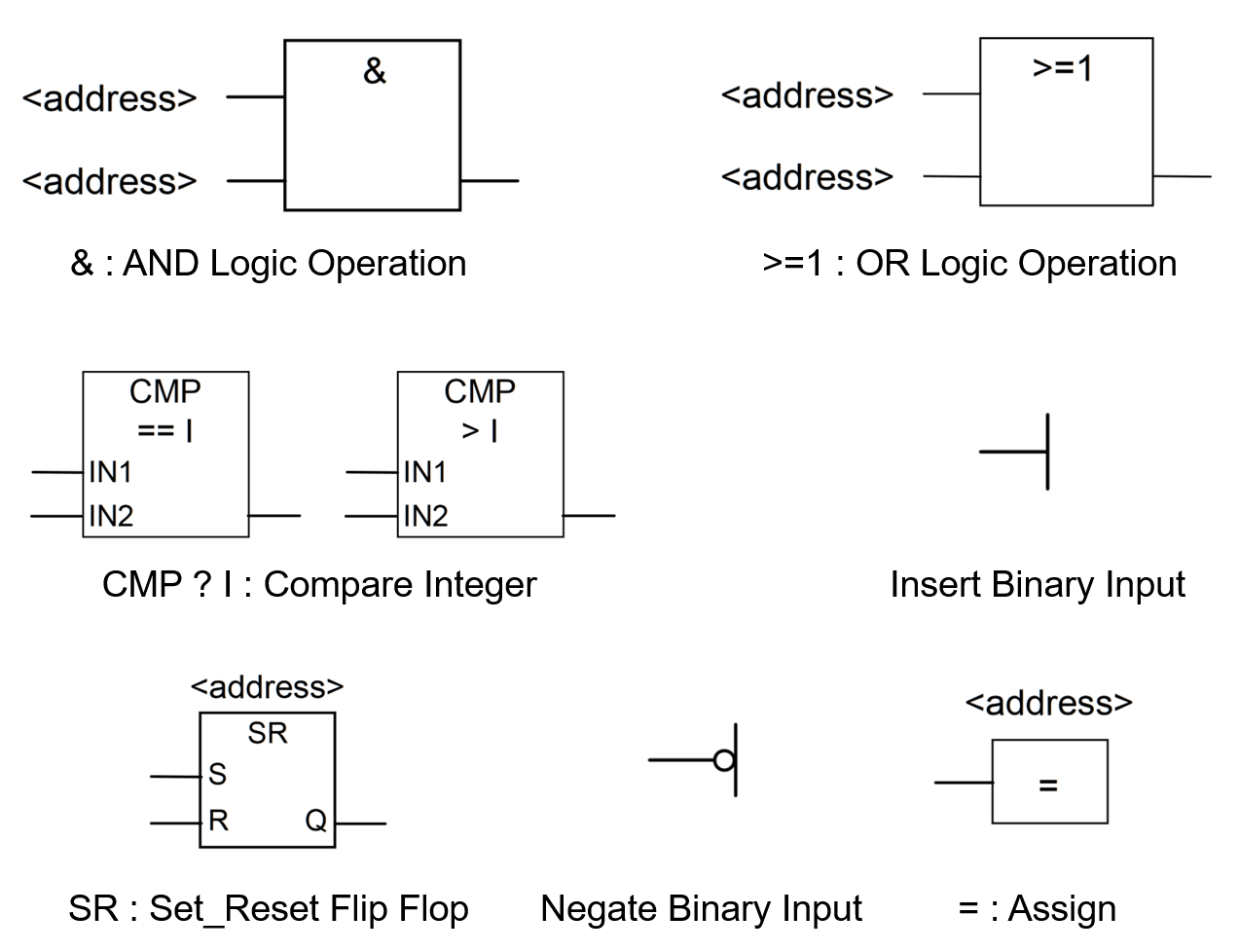
Fig. 34 Common FBD blocks (ref: SIEMENS Function Block Diagram (FBD) Reference Manual)
Additional languages
The Instruction List (IL) is very similar to the programming language Assembler and typically used to limit the computing time. In the example, the operand A is loaded in the working memory in the first line. Next, an AND operation with the negated operand B is conducted. Finally, the result is stored in the variable C. However, IL gets very long and confusing if complex tasks are programmed. As computing time usually does not play an important role today, high-level languages like Pascal, C or Structured Text (ST) are used typically.
The Sequential Function Chart (SFC) can only be used to program sequential control tasks in the form of step chains.
Examples
SCL
A complete example (programming of a traffic light) is shown below. First, an
enumeration including all process states is defined. Next, all necessary
variables are declared (a variable called state is defined using the new
created data type stateType). Finally, the program sequence is established
using a CASE OF statement.
TYPE stateType :
    (RED:=1,REDYELLOW,GREEN,YELLOW);
END_TYPE

VAR
    state:stateType;
    button:BOOL;
    lred,lyellow,lgreen:BOOL;
    atime:TON;
END_VAR
CASE state OF
    stateType.RED:
                IF NOT lred THEN
                    lred:=TRUE;
                END_IF
                IF button THEN
                    state:=stateType.REDYELLOW;
                END_IF
    stateType.REDYELLOW:
                IF NOT lyellow THEN
                    lyellow:=TRUE;
                    atime(IN:=TRUE,PT:=#5s);
                END_IF
                IF atime.Q THEN
                    state:=stateType.GREEN;
                END_IF
    stateType.GREEN:
                IF NOT lgreen THEN
                    lgreen:=TRUE;
                    atime(IN:=TRUE,PT:=#40s);
                END_IF
                IF atime.Q THEN
                    state:=stateType.YELLOW;
                END_IF
    stateType.YELLOW:
                IF NOT lyellow THEN
                    lyellow:=TRUE;
                    atime(IN:=TRUE,PT:=#5s);
                END_IF
                IF atime.Q THEN
                    state:=stateType.GREEN;
                END_IF
END_CASE
Sources
Book Speicherprogrammierbare Steuerungen für die Fabrik- und Prozessautomation, Matthias Seitz, 2012*