Siemens NX MCD
In this module, Siemens NX MCD is introduced and the most common functions that are used in constructing kinematic models are presented.
Learning Outcome
You will get familiar with virtual commissioning.
You will get to know the basics of Siemens NX MCD.
You will understand and be able to create physics-based models.
Virtual Commissioning
Virtual commissioning is the process of testing and debugging control code on virtual models, possibly before the machine/ components materialize. It allows for early validation of code and decreases real commissioning time.

Fig. 35 Influence of control software debugging on project time with (figure below) and without (figure above) virtual commissioning
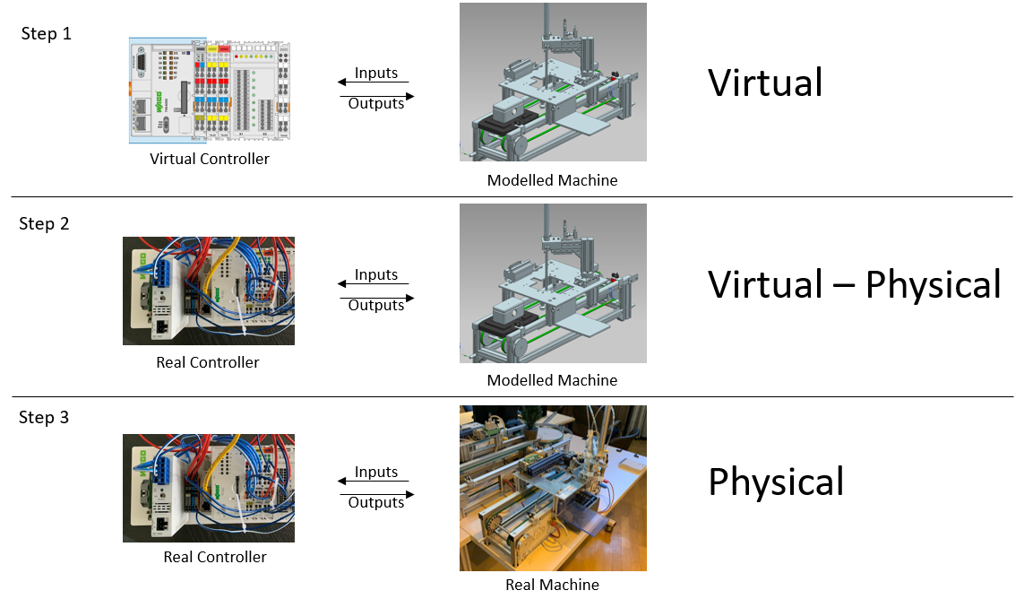
Fig. 36 Typical steps of virtual commissioning
Virtual commissioning can start during the development stages of the product/ asset. At stages where the material objects are not yet available, virtual commissioning allows for early detection of bugs in the PLC code and design flaws in the asset.

Mechatronics Concept
Designer
Siemens NX General Actions
NX is an advanced CAD/CAM/CAE software. The following are some common actions used when working with a CAD assembly in NX.
Action |
How to do it |
|---|---|
Zoom in/out |
Mouse wheel |
Move the view left/right/up/down |
Click and hold both the mouse wheel + the right mouse button and move the mouse |
Rotate the view |
Click and hold the mouse wheel and move the mouse |
Move/Rotate an object relative to other objects/global coordinate system |
Assemblies tab > Move Component > Select Components > Specify Orientation with arrows |
Modelling with MCD
Mechatronics Concept Designer is an application inside Siemens NX that allows the creation of physics-based models and simulations based on CAD files. The goal of the following sections is to guide you through the basics of creating a physics-based model and influencing it from outside the simulation using external signals. To navigate to MCD, open a part or an assembly in Siemens NX. In the Application tab, click on more and choose Mechatronics Concept Designer.
Rigid Bodies
Solids (i.e., CAD models with no assigned physical properties in MCD) are only there to visualize the assembly and do not move during the simulation. Once a part gets assigned as a rigid body, it starts participating in the simulation. As a rigid body, the part is changed from just a CAD model to a part with physical characteristics. Rigid bodies have weight, center of mass and inertia. These parameters influence the dynamics of the body in the simulation. It is recommended to assign a material to the solid body, so that a realistic weight can be calculated.
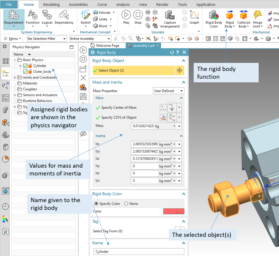
Fig. 37 Assigning a rigid body to a part. One rigid body can consist of multiple parts connected to each other that will always undergo the same motion together.
Rigid bodies react to the acceleration due to gravity, which can be defined along any axis in MCD.
Usually, acceleration due to gravity is defined in the negative z or y directions. The direction of
gravitational acceleration can be changed in File -> Preferences -> Mechatronics Concept
Designer -> General -> Acceleration due to Gravity.
Collision Bodies
Rigid bodies without collision bodies do not collide when they come in contact. Collision is only possible when both objects have collision bodies. Without collision bodies, objects will go right through each other. An object with a collision body, however, will collide with another object that also has a collision body.
Collision is a property which is independent of whether the part is a rigid body or not i.e., a collision object that has no assigned rigid body status will still collide with other objects that have a collision body.
The collision shape of a collision body can be defined in many ways. It is best to choose simple shapes (box, cylinder, etc.) as a collision shape.
Collision mesh
The option “mesh” offers the highest complexity. It allows for a more realistic simulation of the
real object, but requires a high simulation performance. The Convex Factor sets the resolution
of the mesh. The higher the factor, the more detailed the collision mesh. Collision shapes that
consist of more than 300 triangles will automatically set a Siemens NX warning pointing to potential
performance losses.
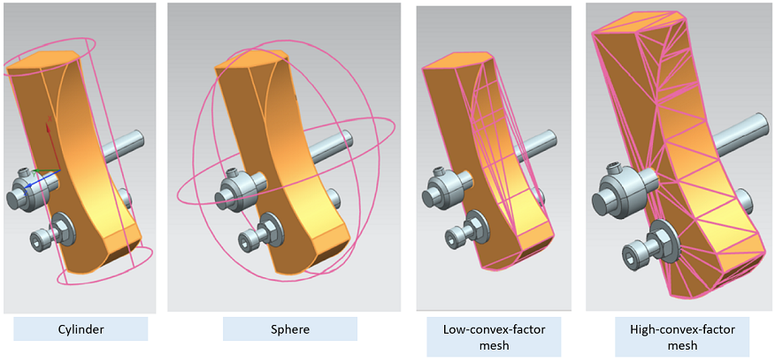
Fig. 38 Different ways to set a collision body; the pink area is the active collision area that will collide with other collision objects.
A decision must be made whether an added complexity to the collision shape serves the purpose of the simulation.

Fig. 39 Assigning a collision body
Category
The category is a number that can be assigned to a collision body to specify collision possibilities with other collision bodies. Collision bodies only collide within the same categories and with collision bodies in the category 0. Category 0 is an exception; bodies in the category 0 collide with all other collision bodies, regardless of the object’s category. Categories can be used to simulate inductive sensors.
Collision material
The choice of collision material influences the physical coefficients dynamic friction, static friction, rolling friction, and restitution. It is recommended to enter accurate friction values for all parts that will take part in collisions to reflect reality.
In order to create a custom material in NX MCD: Go to the Physics Navigator, right click on
Materials and select Create Physics -> Collision Material.
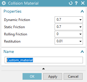
Fig. 40 Creating a collision material
Prevent collision
The prevent collision function allows two collision objects to not collide with one another if they come in contact.
Transport surface
Transport surfaces are used to simulate conveyor belts. Siemens NX MCD provides a function that can define any surface in an assembly as a transport surface.

Fig. 41 Assigning transport area properties to a surface
Collision Sensors
One of the sensor functions available in Siemens NX MCD is a function that turns objects into collision sensors. When such an object collides with another object (the second object must have collision properties), a boolean signal is set to true. Collision sensors are used to simulate different types of real life sensors (e.g., optical sensors, inductive sensors, etc.). Collision sensors are usually helping elements and are not displayed (blinded out) during the final simulation.

Fig. 42 A collision sensor used to simulate the function of an inductive sensor in the assembly. The sensor detects if a part is at the beginning of the conveyor belt.
Joints
Rigid bodies can be fixed, positioned in space or connected to each other by joints of different degrees of freedom. These connections are independent of the assembly constraints from the design application. The joints are available in different degrees of freedom: Hinge (swivel joint f=1), sliding joint (f=1), and cylindrical joint (combined sliding joint and hinge (f=2)).
The following figure shows a sliding joint that is assigned to a rigid body. The rigid body has only one degree of freedom and can be moved only along the axis specified for the sliding joint. Moreover, upper and lower limits are defined along the specified axis which the body cannot exceed during motion.
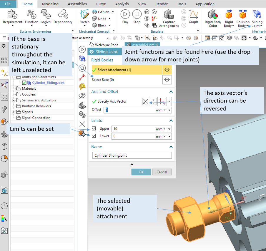
Fig. 43 Assigning a sliding joint to an object
The following figure shows a hinge joint assigned to a part within an assembly. For a hinge joint (and a sliding joint), an attachment object and a base object should be provided. A base object can be ignored if the base of rotation (or sliding) is not movable in the simulation. In case the base is movable, it must be specified.
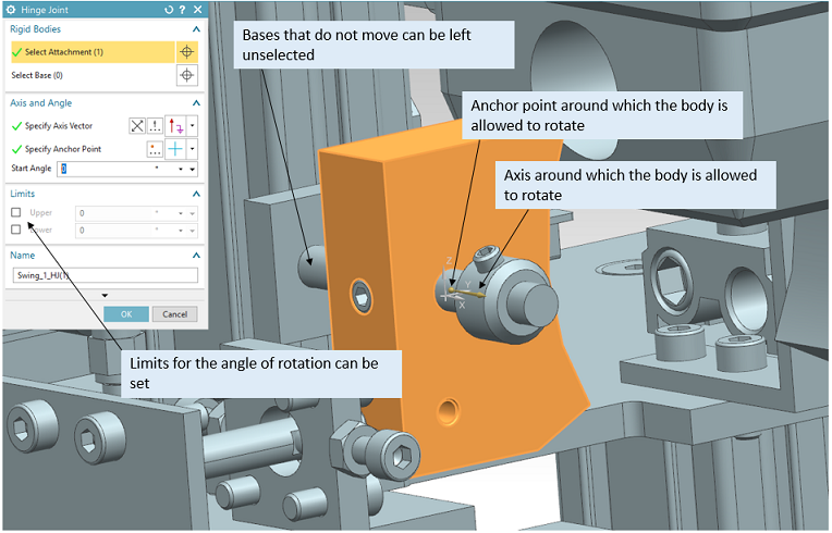
Fig. 44 Assigning a hinge joint to an object within an assembly
Position Controls
The positions of the joints created earlier can be controlled with objects called Position Controls,
which can be found in the Electrical tab. The following figure shows the creation of a position
control object to control a sliding joint object.

Fig. 45 Creating a position control to control the position of an object along its sliding joint
Position controls can also be created to control the angle of a hinge joint. Position control objects have two important variables: position and speed. Both variables can be manipulated during the simulation using operations and external signals.
Signals
Signals are objects that allow the communication to programs outside of the simulation. A signal in MCD can have the type bool, int, or double. A signal can be an input signal or an output signal, allowing a two-way communication from and out of MCD.
Note
When communicating with a PLC, an output signal from the PLC’s perspective (for example, an motor_on signal) is an input signal from MCD’s perspective and should be defined in MCD as an input signal.
Signals can be linked to runtime parameters, in case of a collision sensor for example, where the collision sensor’s value (true/false) is the runtime parameter. Signals can also trigger action in the simulation, e.g. setting a motor to turn on. When interacting with a PLC, an MCD signal should be created for each PLC input and output variable. In order to allow auto mapping procedures and prevent confusion, the names of the signals both in the PLC program and in MCD should be identical.
The following figure shows an input signal (input into MCD, output from PLC) that is meant to control the cylinder’s position.
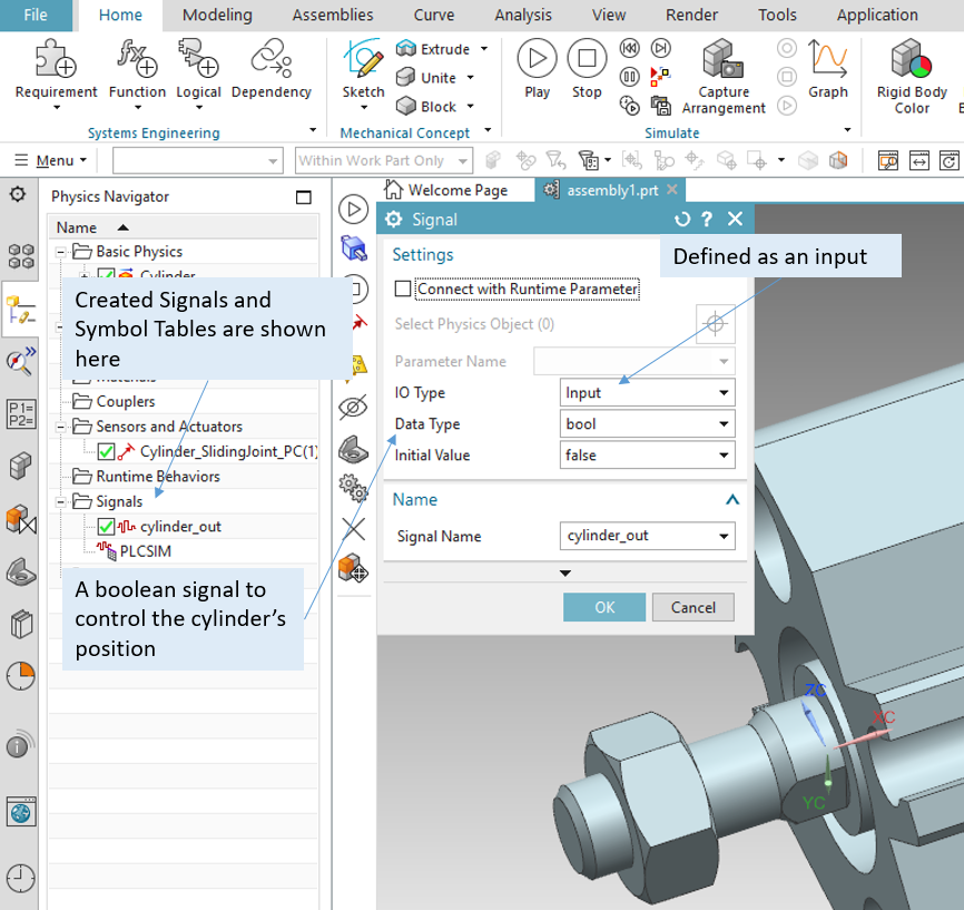
Fig. 46 A boolean input signal
Symbol Tables are tables that show related signals together. They are a way to not lose track of signals.
OPC UA and Signal Mapping
To establish a communication over OPC UA, click on External Signal Configuration from the
Automation tab. The following figure shows the configuration of an OPC-UA communication.
Two boolean variables are selected which are relevant to the given simulation.
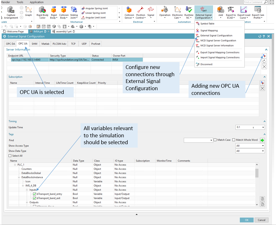
Fig. 47 External signal configuration
Note
To be able to communicate to a simulated PLC over OPC UA, make sure that OPC UA is configured in the PLC. (See section on TIA Portal basics)
Now that the external signals are imported, it is time to map them to the signals that were created inside MCD. The following figure shows auto mapping of 3 inputs and 2 outputs (from MCD’s viewpoint).
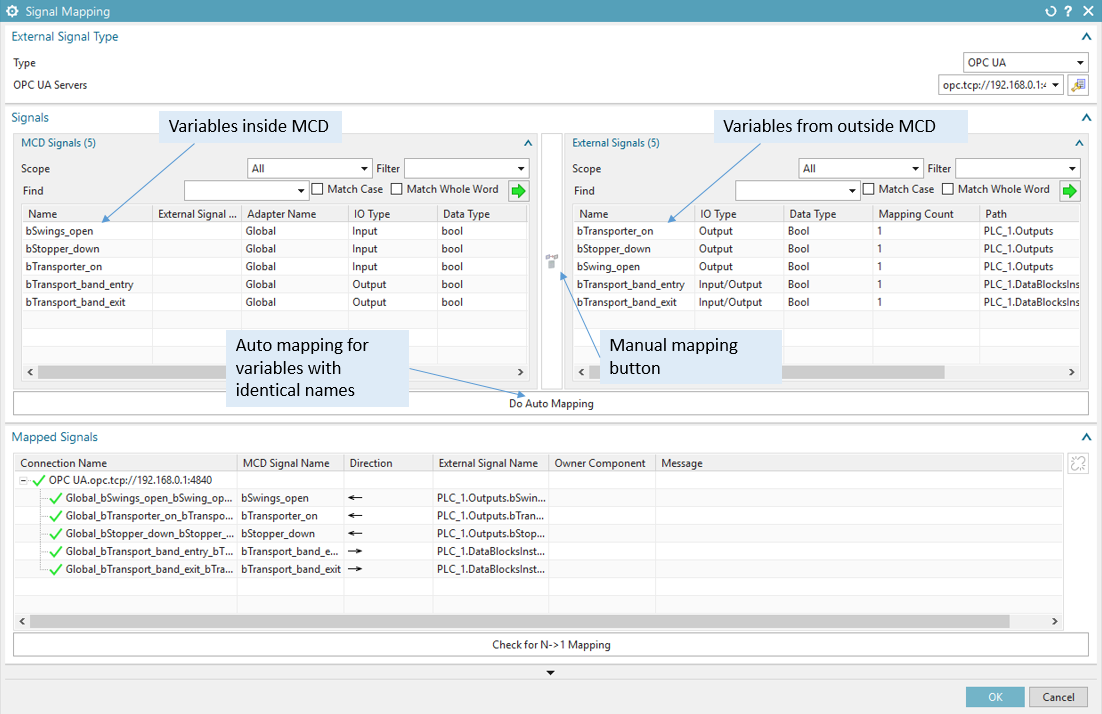
Fig. 48 Signal mapping
Operations
Operations are one way to allow external or internal signals to manipulate the simulation in real time.
The following figure shows an operation that influences the value of the position variable of a position control object. The shown operation extends a cylinder. The condition object is an MCD signal that is mapped to an external signal. Thus, this cylinder can be controlled from outside the simulation while the simulation is running.
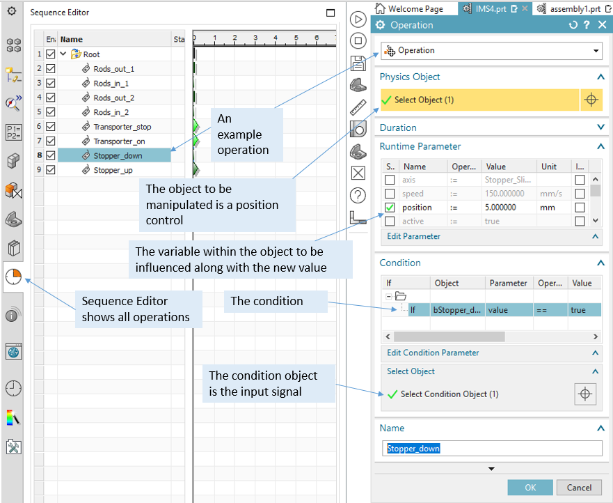
Fig. 49 An example of an operation to influence a position control during simulation in real time
A Note on Assembly Hierarchy
The following figure shows a robotic arm in an assembly. The robotic arm itself (UR3_step) is
an assembly that is made of single parts. The robotic arm is part of a bigger assembly
(called assembly1). In this example, assembly1 is the main assembly (the biggest assembly)
and the robotic arm is a sub-assembly inside that main assembly.
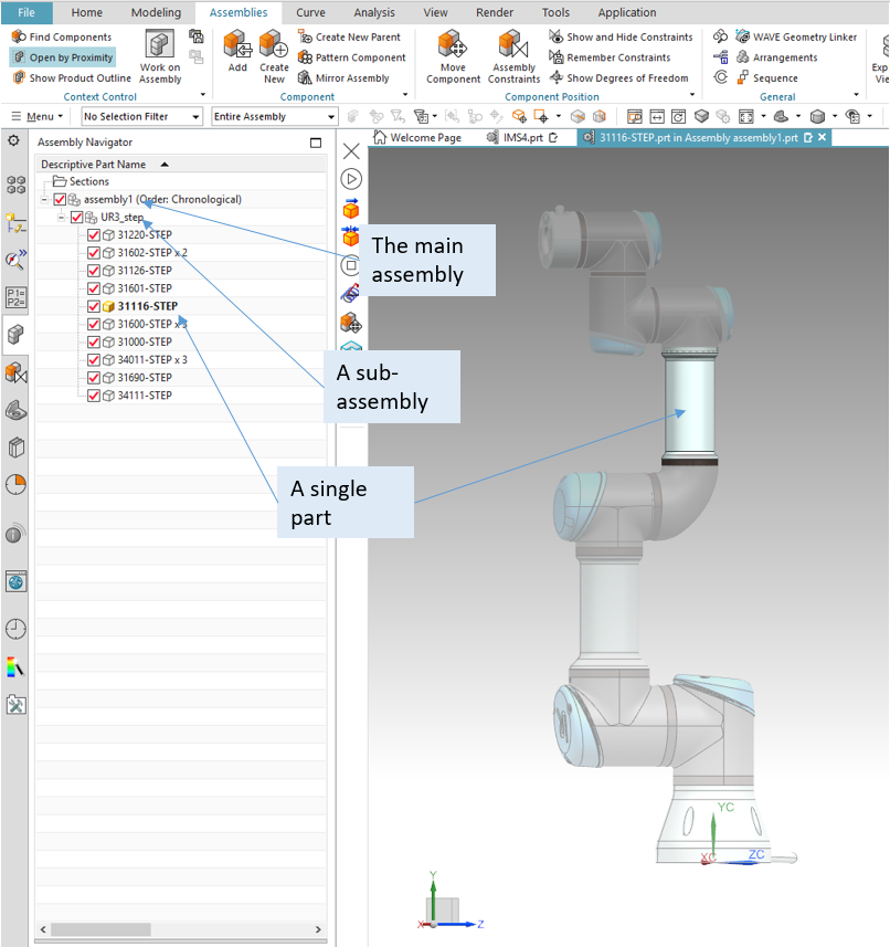
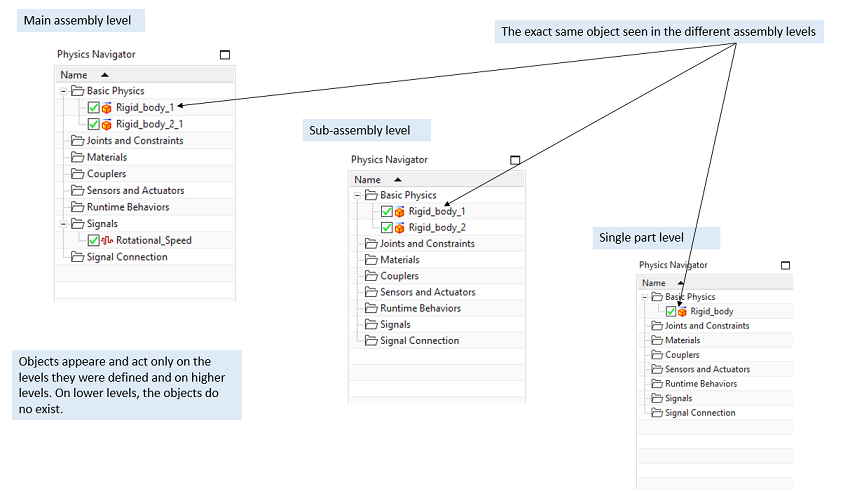
Fig. 50 Assemble levels
Assemblies can thus include single parts or other sub-assemblies.
By double clicking on a part/assembly, MCD focuses on that selected part/assembly. Simulations only run with the selected part/assembly. To run a simulation including all parts, the main assembly has to be selected. To run a simulation for only one part/assembly, that part/assembly has to be selected.
The location of a single part in the hierarchy can be changed through drag and drop between the assemblies.
The creation of physical properties (rigid bodies, collision bodies, joints, signals etc.) in Mechatronics Concept Designer can be done on any assembly level. Copying parts between files will retain the physical properties created on the copied level and on all lower levels copied along, but not the properties that were created on higher levels.
When a model is copied, the physical properties of all lower levels are copied along.
Assigning properties on the individual part’s level is handy if the part is going to be reused in many other assemblies. This way, the part can retain it’s physical properties. This saves the work of reassigning physical properties to the part each time it is copied into a new assembly.
Assigning the properties on a higher level in the assembly is handy if the part will be used in other assemblies but its properties are not needed anymore. This saves the work of manually deleting all the assigned properties when copying the part into a new assembly.
Because of a bug that causes a communication problem, it is recommended to assign physical properties to parts in a sub-assembly level or on the main assembly level. It is advised to avoid running the simulation on a single part level. Refer to the section on Troubleshooting for more details on communication bugs.
Summary
Siemens NX MCD offers a tool to create kinematic models using existing CAD models. These kinematic models can be controlled by PLCs (simulated/real), which allows for early verification of control code and a cut in real commissioning time.