TIA Setup
The setup of Siemens PLC is done with the help of TIA Portal application
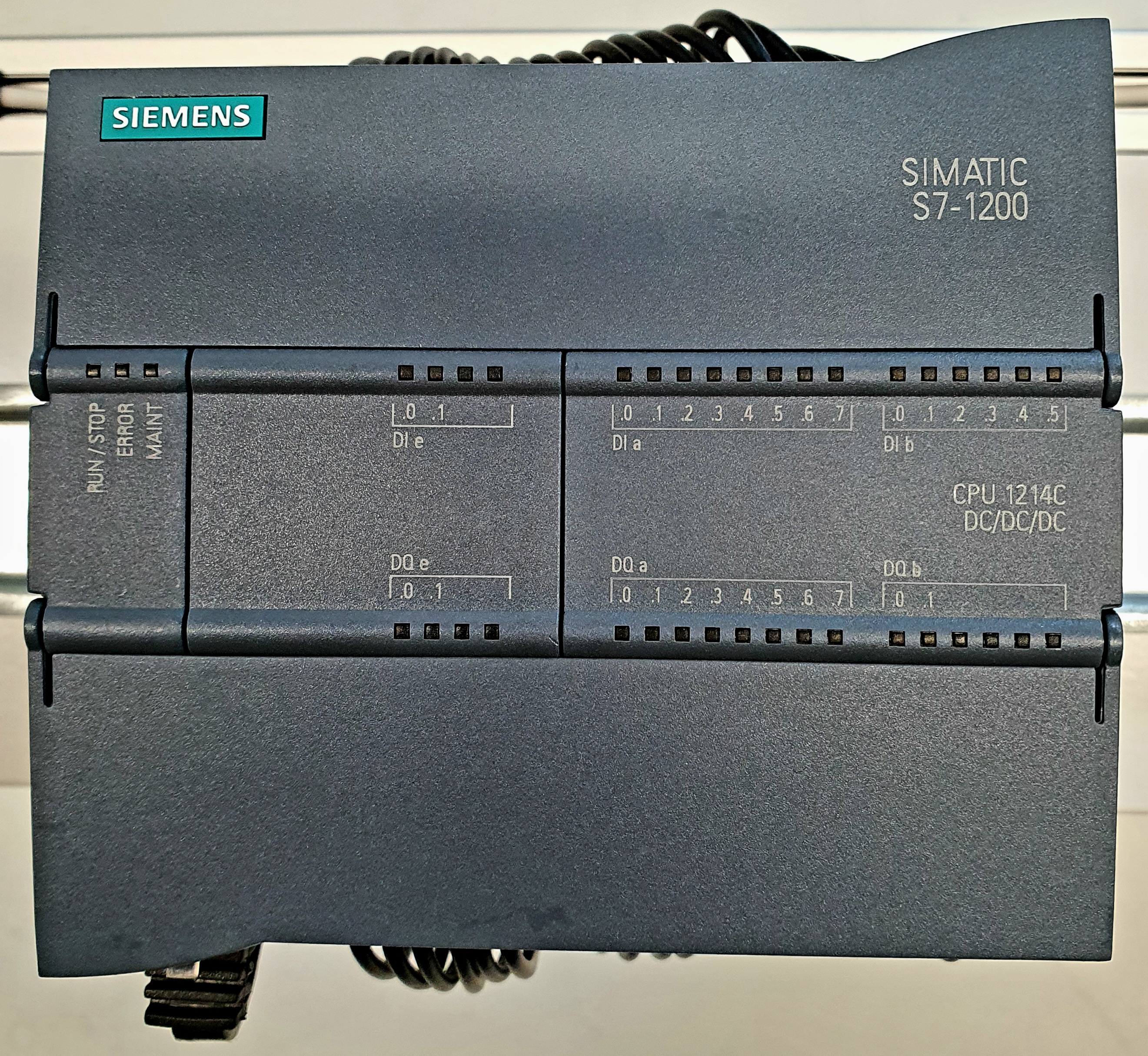
Fig. 59 Siemens PLC S1200
TIA Portal is a Siemens software for programming PLCs.
Creating a new project
To create a new project inside TIA Portal V16, click on Create new Project
from the start menu and provide name, path in which the project will be saved, and
an optional comment.
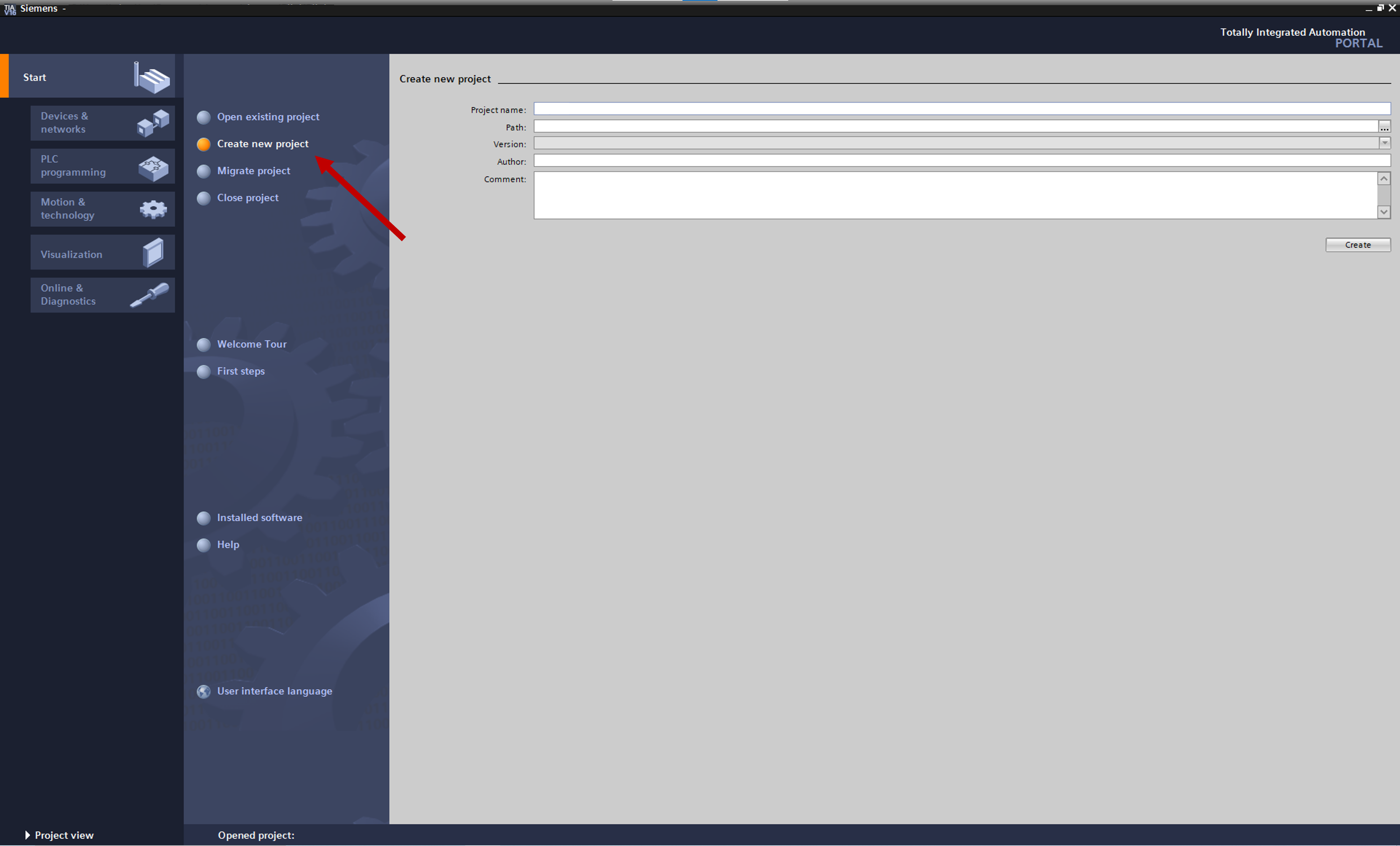
Fig. 60 TIA Portal Startup interface.
Following this, guided project creation steps will show up on the screen.
Adding a PLC to a project
To add a PLC to the current project, first find the model of the PLC. Click on Configure networks under Devices & networks from the menu.
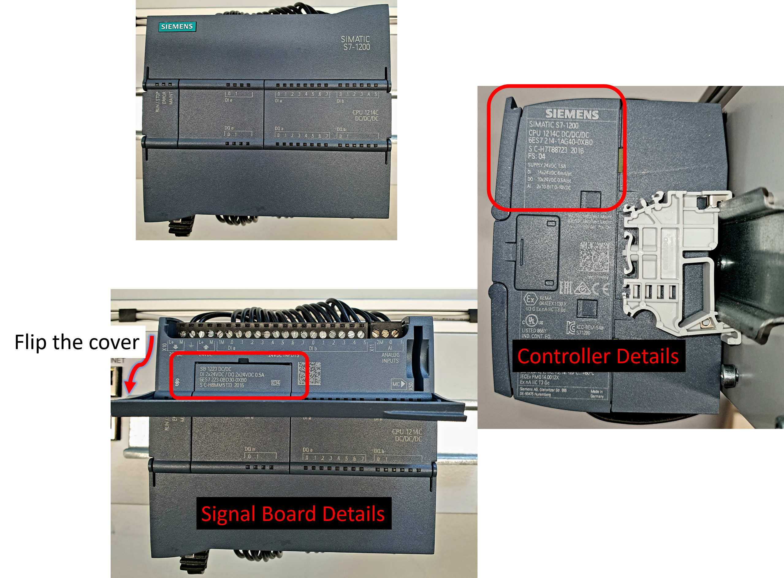
Fig. 61 PLC Setup in Project part 1
- Once done, follow the steps below to add it (images added for reference):
Click on
Configure networksGo to
Online->Accessible devices.... A pop-up window will open.Select
PN/IEinside Type of the PG/PC interface:. Check for the PG/PC interface and set it to LAN connection from drop down list. For example, Intel(R) PRO/1000Click on
Start searchto find connected devices to computer’s LAN. Once scan is complete, you will see a device in the list with properties like Address, MAC Address etc. Read the IP Address on your PLC and find it in the list. It should be like192.168.##.##.To confirm it’s your device, click on the device and press Flash LED. You will then see the Power LED on PLC starts to blink. This confirms that you have selected your own PLC. Next click on
Show.
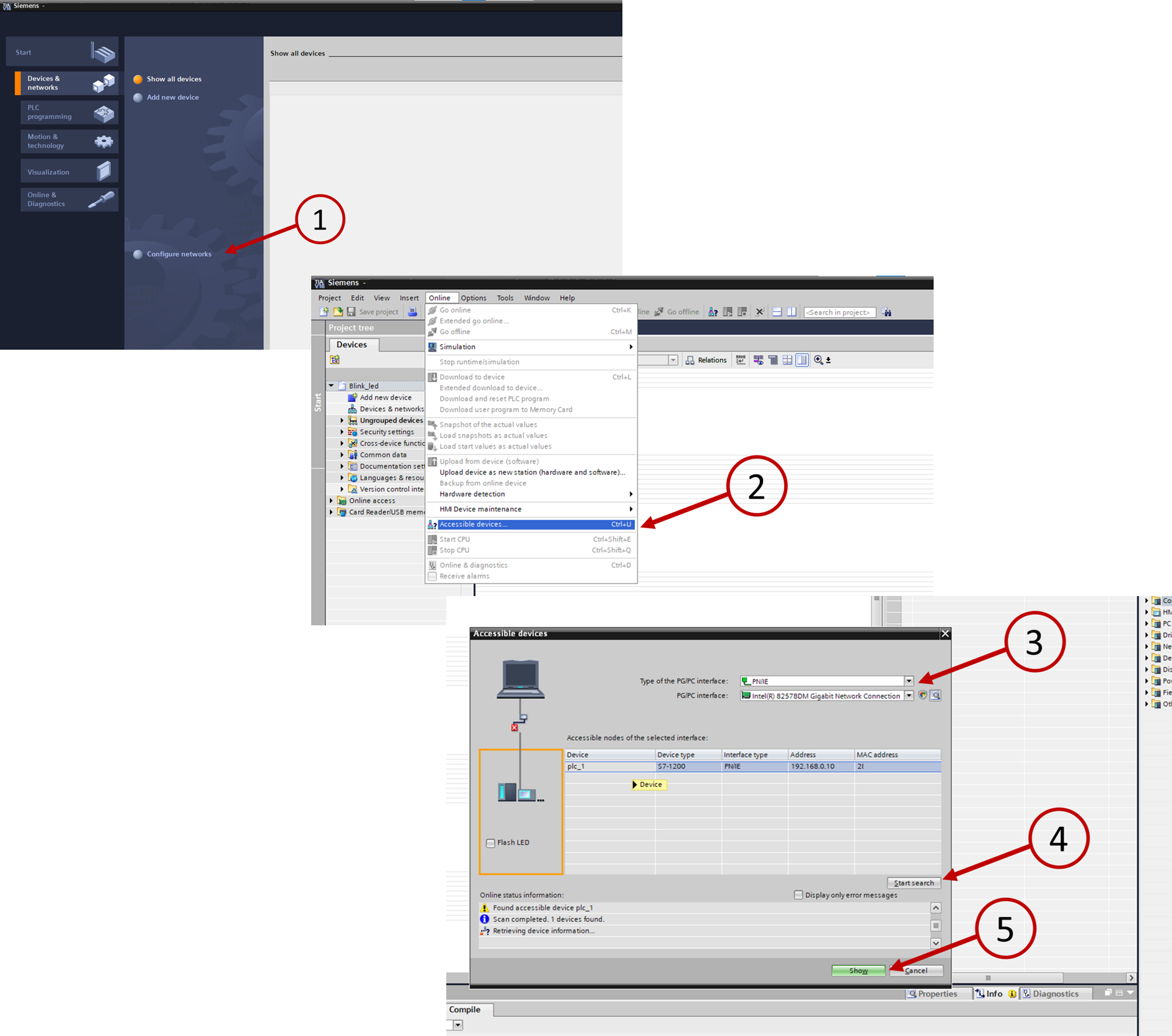
Fig. 62 PLC Setup in Project part 1
The pop-up window closes and on the left side, a tree list (project tree) structure expands. Here you will find the PLC you selected.
Expand the tree of the PLC and double click on
Online & diagnostics. A new window opens with details about the PLC.Check for the Firmware version and note it down.
Click on
Portal viewand return to theAdd new devicepanel.Click on
Add new deviceSelect the correct PLC from the list and use the correct firmware version.
Once done, click
Addand the selected PLC will be added to your project.
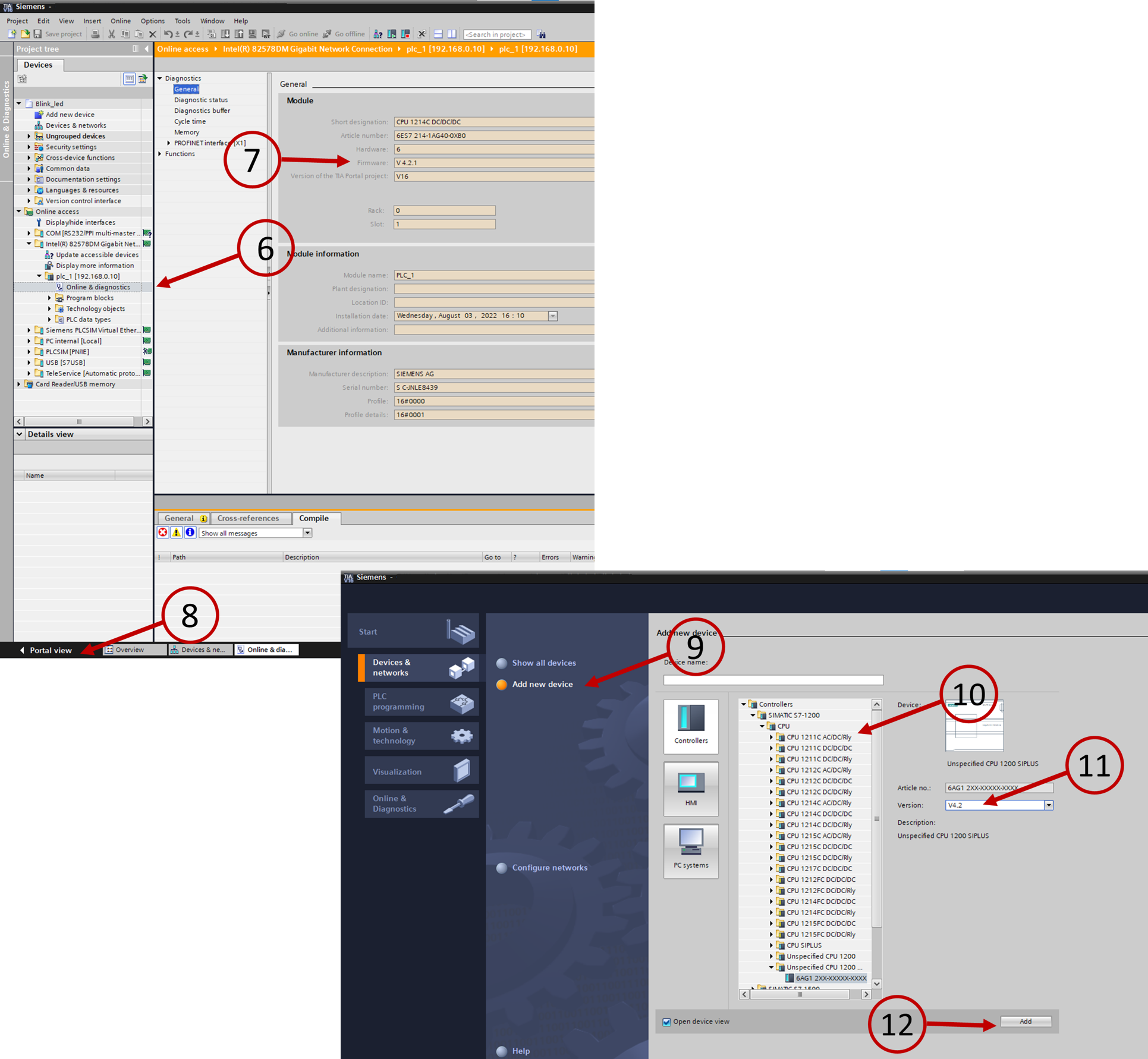
Fig. 63 PLC Setup in Project part 2
Adding a signal board to PLC
A new window will open with image of the selected PLC. Go to
Device viewif not already there.Click on the center of the PLC to add signal board.
From the catalogue on the right side, select the correct signal board and drag it on the top of the center of the PLC. You will mostly find the right board in
Signal boards->DI/DQ.Now your PLC is ready to be programmed.
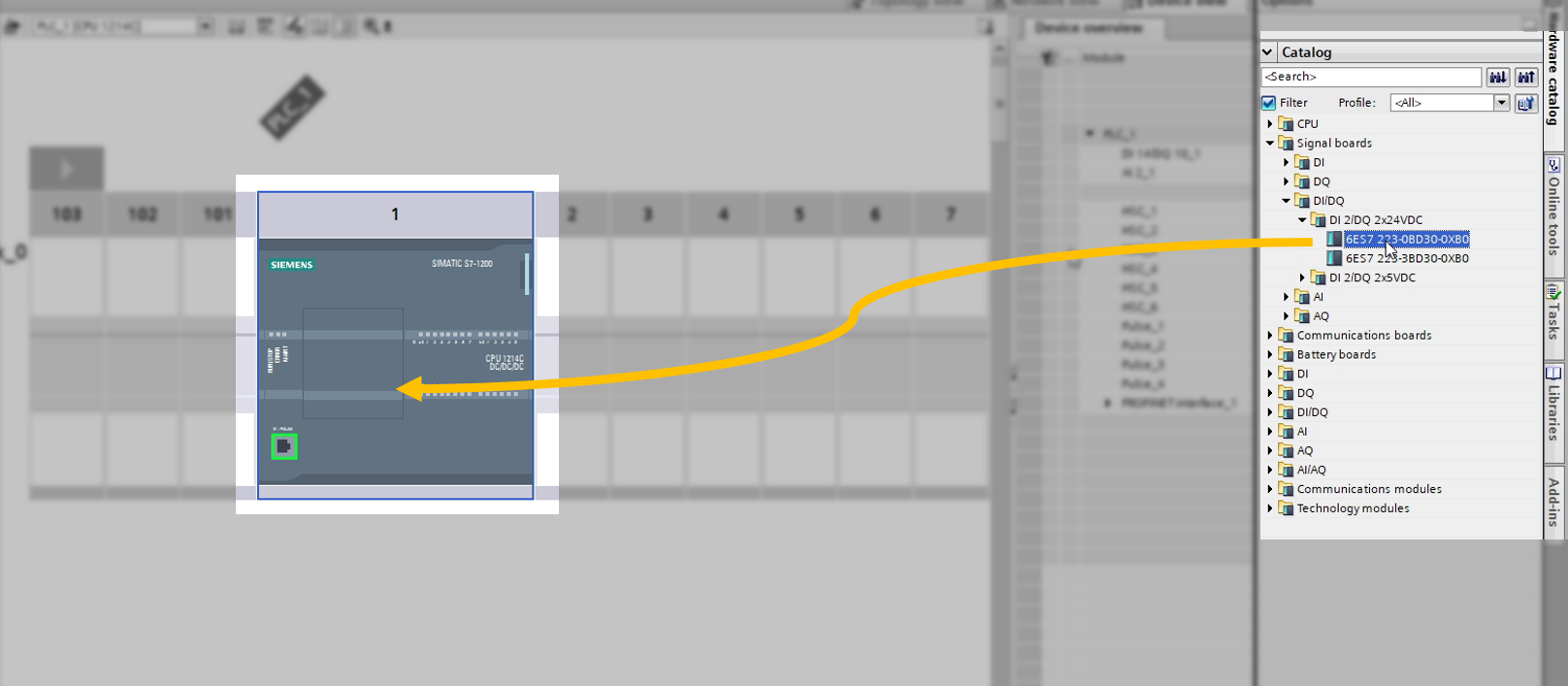
Fig. 64 Adding signal board to PLC
If the version is not visible, use the following configuration provided with the PLC.
Once everything is set, the PLC should look like this.
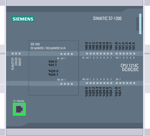
Fig. 65 PLC after setup in TIA Portal
Changing IP address for Project
- To change the IP-Address of the project, follow the steps below:
Right click on the PLC from the left side project tree.
Click on
Properties. A pop-up window will open.In that window, find
PROFINET interface->Ethernet addressess->IP protocolHere, enter the
IP address:provided with the PLC. ClickOKonce done.
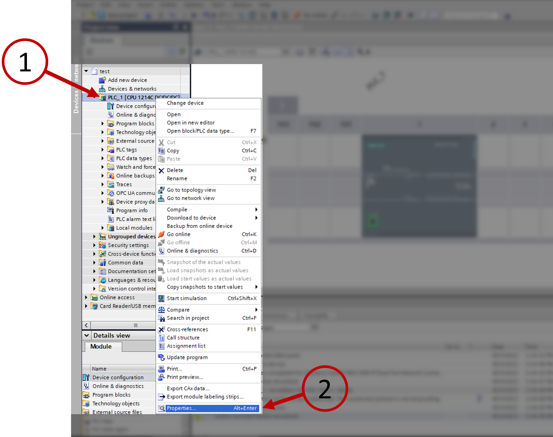
Fig. 66 Change IP of project part 1
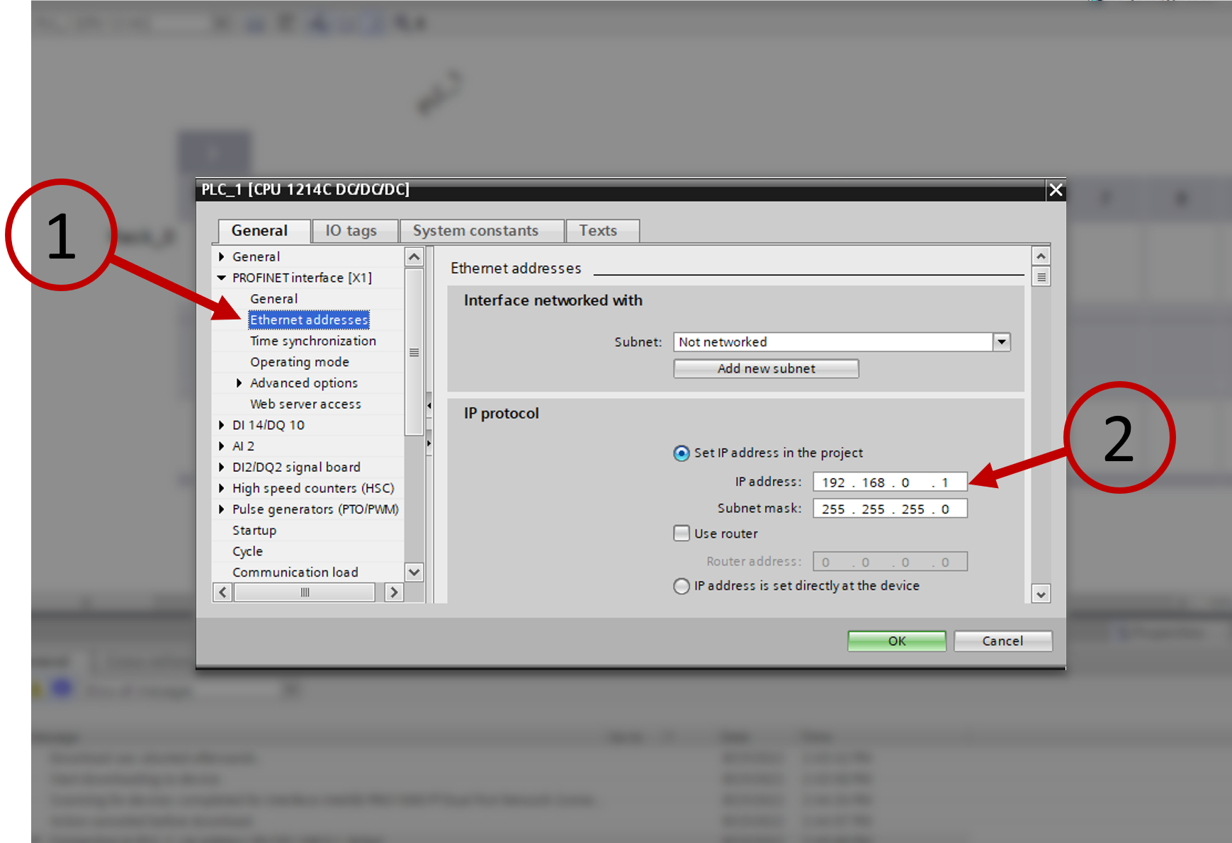
Fig. 67 Change IP of project part 2
Uploading code to PLC
- Initially you will have to add the plc on your network, to your code. To do that and to upload the code for the 1st time, follow the steps below (images added for reference):
To upload code to PLC, select the PLC from the left project tree structure.
Select
Online->Download to deviceoption from the menu. A pop-up window will open.Check for the PG/PC interface and set it to LAN connection from drop down list. For example, Intel(R) 82578DM
Click on
Start searchto find connected devices to computer’s LAN.Once scan is complete, you will see a device in the list with properties like device name, IP Address etc. To confirm it’s your device, click on the device and press Flash LED. You will then see the Power LED on PLC starts to blink. This confirms that you have selected your own PLC.
Click on
Loadbutton. This will compile your code and show the possible errors and warnings. Once the code is checked, this will upload the code to the PLC. After that, click onFinishto close the pop-up window.
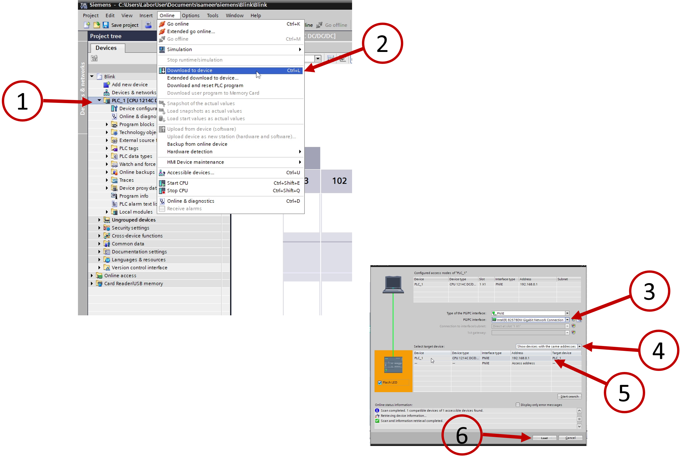
Fig. 68 Uploading code to PLC for 1st time
Note
Keep the PLC connected with LAN cable.
When uploading any hardware changes, keep the PLC in
STOPmode and in offline mode. i.e.,Online->Stop CPU&Online->Go offlineWhen uploading only software changes, you can keep PLC in Online mode.
Note
When uploading to a Virtual PLC, switch to Siemens PLCSIM Virtual Ethernet Adapter in #Step 3. Rest of the steps remain same.
After uploading for the 1st time, you can now upload only software changes until you don’t have any new hardware configuration or hardware property changes.
To do so, right click on the main code block and click on Download to device -> Software (only changes)
If you have hardware changes or property changes, right click on PLC name from the left project tree. Click on Download to device -> Hardware and software (only changes). You might have to Go offline and then Online to see the changes.
Creating PLC tags for Pins
PLC tags are the PLC variables. These particular variables are mapped to the PLC I/O modules. Tag tables are used to view the PLC tags. One can add new tag tables to sum up variables that are related together. When a variable needs to be connected to a physical signal that is outside the PLC (e.g., a sensor reading coming in), it is defined in a PLC tag table.
- To define project tags,
Go to the left side project tree. Expand the PLC and expand PLC tags.
Under this, click on
Add new tag table. Rename the new table with a proper name for example, out_pins.Double click on the table name, a new pop-up window should open. Here you define variable names for the pins you wish to use in your programs. A sample list is shown below.
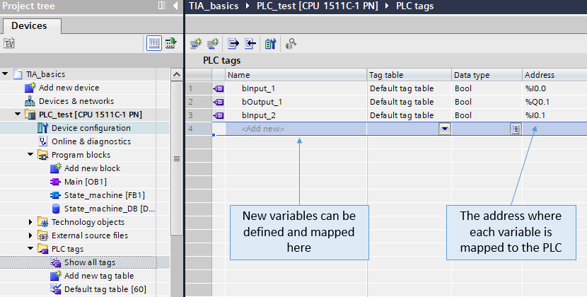
Fig. 69 Defining PLC Tag
Note
This section supports features like drag to add sequential list like MS Excel.
You can also import & export this tag table from & to MS Excel or other spreadsheet application.
Note
- You will see the following in Address column
I -> Input pin
Q -> Output pin
M -> Memory location
When you add variables for input/output pins of PLC, they also replace on PLC in Device View.
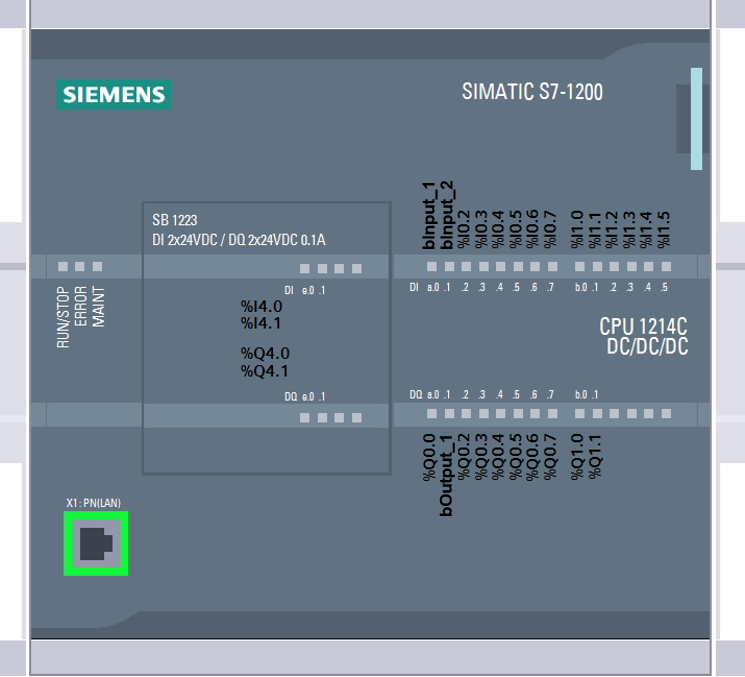
Fig. 70 Device view after variables to Tag Table