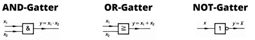
Pneumatics and the Digital Module
Logic modules
Todo
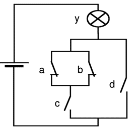
Implement the contact logic shown with logic modules (inputs d, c, b, a / output y).
Hint
If you want to test your contact logic in FluidSim, you can use the setup shown in the following figure.
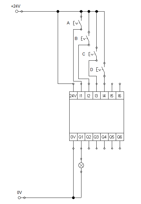
Pneumatic feed drive with digital module
A feed drive with pneumatic components is to be implemented that operates under certain conditions.
The feed drive is implemented by a cylinder that returns to its home position when depressurized
The piston speed is influenced by means of a control element
- The piston may only extend if the following conditions are met:
A two-hand control must be ensured (Two pushbuttons must be permanently actuated during the feed movement. This ensures that the operator’s hands are out of the danger zone).
The piston is not in its end position.
As soon as the end position is reached, the piston automatically retracts completely (even if both buttons are still pressed).
Todo
Create a circuit in FluidSIM with the specified properties and realize the program logic by means of a digital module.
Todo
Create the whole logic in the digital module; do not add logic outside (e.g. by using normally closed contacts or parallel paths )
Industrial roller shutter door
Description:
The rolling gate is opened and closed by the gatekeeper using an “up” and “down” button.
The movement can be interrupted at any time using a STOP button.
Two motors are used: One motor for the movement upwards, one motor for the movement downwards.
When the gate is fully open or closed, the motor is switched off.
An indicator light shows the operation of the door 5 seconds before the movement and during the movement.
A safety pressure bar ensures that the gate stops on contact, immediately moves up and stops at the top.
Todo
Create a principle sketch of the rolling gate
Todo
Create the circuit diagram with logic gates in the digital module and with the hardware components (motors, pushbuttons, etc.)