10. Station IMS7: Practical Assignment
10.1. Goal
To create a physics-based model of the IMS7 station
To implement the state machine of IMS7 in a TIA Portal program
To control the physics model with the created state machine program via OPC UA
10.2. IMS7 Station Functionality
The purpose of the IMS7 station is to pick-and-place the end-product from the assembly line onto an outside platform. It does so by using a vacuum gripper and a rotating arm to lift the end-product and re-place it on the platform.
The station has a few sensors and actuators, shown in the following figure.
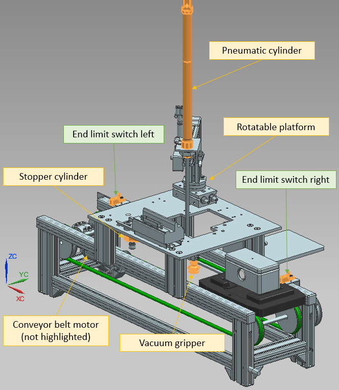
Fig. 10.1 Sensors and actuators on the IMS7 station
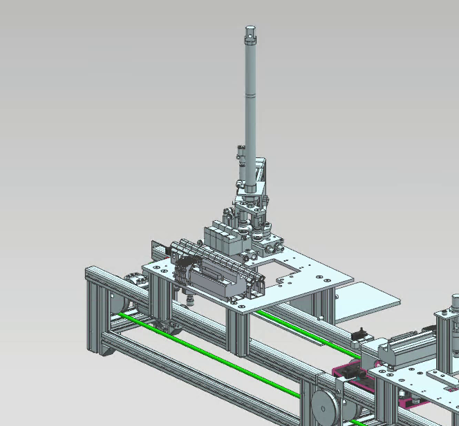
Fig. 10.2 The station’s functionality
10.3. The Virtual Layer - Mechatronics Concept Designer
Physical properties should be assigned to different parts of the IMS7 station.
Open the assembly file called ASSEMBLY_IMS7.prt in Siemens NX and navigate to the
Mechatronics Concept Designer application.
10.3.1. Top part, base part, bolt, and workpiece carrier
Assign rigid bodies to all parts that are going to move/collide during the simulation of the station. All parts that will not move/collide during the simulation should be ignored.
Rigid and collision bodies
Todo
Assign rigid and collision bodies to the top part, the base part, bolt, and the carrier.
Note
When assigning rigid bodies to part, a few parts can be selected together and defined as one colelctive rigid body. This should be done if those parts will always undergo the same motion together.
Note
When assigning collision bodies to parts, only sides/areas of the part that will undergo collision during the simulation should be chosen. Avoid defining the entire part as a collision body, because it increases the complexity of the body and unnecessarily slows down the simulation.
Note
When assigning collision bodies to parts, try to choose simple geometry (box, cylinder, sphere, etc.) if complicated geometry (mesh) is not crucial for the physical behaviour of the part.

Fig. 10.3 An example of collision body assignment. Collision surfaces are shown in pink. The upper part has a simplified geometry and surfaces on the part that will not undergo collision were not chosen, which reduces the complexity.
Todo
Assign a collision body to the platform that receives the end-product.
10.3.2. Conveyor belt
To simulate a conveyor belt, a rectangular surface will be used as a Transport surface. The band itself will be blinded out while the simulation is running.
Todo
Assign a Transport surface to the part 200213_TransportflaecheDUMMY. Do that on the
Entire_Transport_Band level.
10.3.3. Pick and place mechanism
Rigid and collision bodies
The entire arm rotates to bring the end-product to the specified platform. Because all components of the arm undergo the same motion together at all times during the simulation, they should be defined as a unified rigid body.
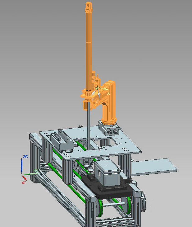
Fig. 10.4 The entire arm is defined as one rigid body
Note
Because the cylinder’s rod will undergo a different motion than the rest of the arm, it should not be included in the same rigid body definition. The cylinder’s rod should be defined as its own rigid body.
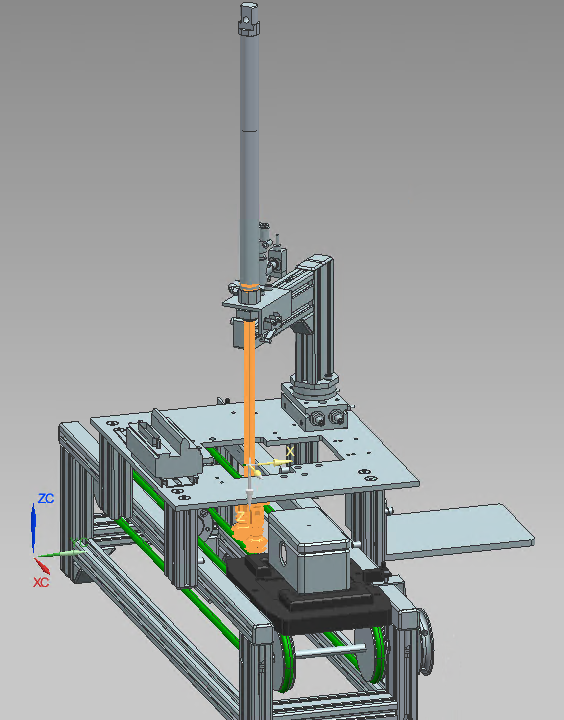
Fig. 10.5 The cylinder’s rod is its own rigid body
Todo
Assign a rigid body and a collision body to the cylinder’s rod and to the stopper’s rod.
Joints
Todo
Assign a sliding joint to both the cylinder’s rod and the stopper’s rod and enter appropriate limits.
Note
Does the base object have to be specified in both cylinder’s cases? Why or why not?
Todo
Assign a hinge joint at the rotating part of the arm.
Special joint case: vacuum gripper
A fixed joint should be created between the gripper and the top part being picked up. Because those two parts belong to different sub-assemblies, only the base of the fixed joint (the gripper) should be given when creating the fixed joint. The attachment of the fixed joint (the product) should be assigned to the fixed joint later during the simulation using an operation.
The top part is connected to the bottom part through a magnetic contact in addition to the bolt. The magnetic contact will also be simulated using a fixed joint.
Todo
Create a fixed joint between the gripper and the top part. Create another fixed joint between the top part and the base part. At first, give in only the base objects (the gripper for the first fixed joint and the top part for the second fixed joint respectively). Manipulate those fixed joints by adding their attachment objects later in the simulation when the gripper is supposed to lift the product using an operation (see section on operations).
Todo
Optional task: is there a way to let the product fall (switch off the fixed joint) if the product’s weight exceeds a certain limit? Describe the approach briefly.
Position controls
Todo
Assign position control objects to each of the joints.
Signals
Todo
Assign signals to each of the position control objects.
Operations
Operations are like if-statements in the MCD simulation. They can be used to trigger something in the simulation if an external (or internal) condition is met.
Note
Operations can be found in the Sequence Editor menu on the left.
Todo
Create an operation to send the stopper cylinder down. Call it Stopper_down_operation for clarity.
The selected physics object of the operation is the stopper’s position control.
The runtime parameter selected is the position, because this is the parameter to be manipulated by the operation.
The new value is inserted in the Value column. Under Condition, the condition object selected is the signal
that was created to control the stopper.
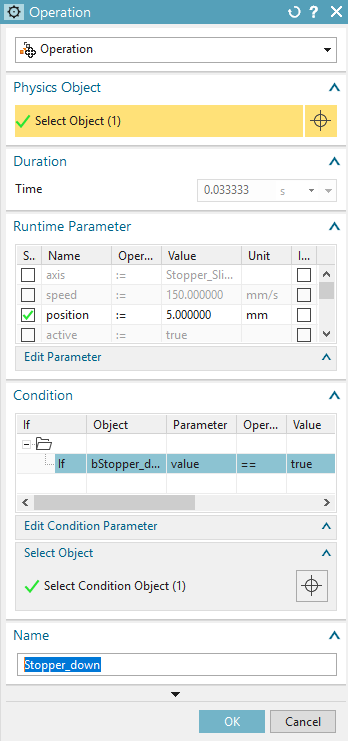
Fig. 10.6 An operation to send the stopper’s sliding joint to position 5mm if the signal bStopper_down is true.
The equivalent in C++ would be:
if(bStopper_down == true) {stopper_sliding_position = 5;}
Todo
Create operations to rotate the arm, drive the pneumatic cylinder down, and turn on the gripper (turn on the Stick
when Collision property of the gripper’s collision body).
Todo
Determine the position control values by measuring the length of the rod and taking the start position into consideration.
10.3.4. Sensing Mechanism - Entry and Exit Sensors
Collision Sensor
The IMS7 has entry and exit sensors at the start and end of the conveyor belt (see section on IMS7 Station Functionality).
These two sensors will be simulated as two small cubes with collision sensor properties.
Create a new block in mechanical concept under the Home tab. Give the block the dimensions of 10mm x 10mm x 10mm.
Under the Assemblies tab, click on Create New to create a new model. Name the model something appropriate, like
end_limit_switch_dummy and click OK. To select the block just created, navigate to Part Navigator on the
left-side menu and choose the block that was just created. Now the block is a model and can be seen in the
Assembly Navigator. Choose Move Component under the Assemblies tab and move the new block to where
the sensor is supposed to be.
Note
When moving an object, clicking on Specify Orientation will enable you to drag on the three axis to move the object.
Now that the dummy-sensor is in place on the conveyor belt. Assign a collision sensor to it. Be sure to call the collision
sensor something appropriate, like End_limit_switch_right.
Signal
For the dummy sensor to send its reading to the PLC, a signal should be created.
Todo
Create a boolean signal and connect it with a runtime parameter. The physics object selected should be the
End_limit_switch_right object. Be sure to define the signal as an Output, since it is an output from
MCD’s perspective.
Note
It is important to give the signal a clear name. For example: bEnd_limit_switch_right.
Where b in the beginning stands for boolean.
The entry sensor is done for now. Later, End_limit_switch_right will be mapped to a PLC signal with the exact same name.
Todo
Go through the same steps again and create a second sensor to detect the carrier’s exit. Call the new sensor signal
bEnd_limit_switch_left.
10.4. The Physical Layer – PLC Program
A program to control the IMS7 station can be found in the downloads. In this module, a PLC will be simulated to control the station.
10.4.1. TIA Portal
The following figure shows a state machine diagram for the IMS7 station. This state machine is implemented in the program.
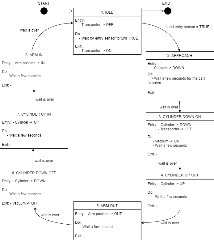
Fig. 10.7 A state machine diagram for the IMS7 station’s functionality.
Todo
Open the program in TIA Portal.
Note
Outputs of the MCD Simulation are inputs of the IMS7 function block, and vice versa. Use the same exact
names that are used in the variables in the IMS7 function block in the MCD simulation also.
This allows for auto-mapping later.
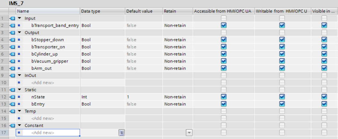
Fig. 10.8 Variables of the IMS7 function block
10.4.2. PLCSIM Advanced
Todo
Start PLCSIM Advanced and start a PLC simulation.
Note
Make sure the PLC simulated has the same name as the PLC in the TIA Portal program.
Note
Make sure PLCSIM Virtual Eth. Adapter is selected.
In TIA Portal, compile your program and upload it to the simulated PLC.
10.5. Controlling the MCD Application using the PLC Program
Todo
Make sure an OPC UA server is configured in the PLC program and connect to it in MCD. When including variables from the PLC program through OPC UA, choose the variables that you need to control the simulated production station.
Todo
In the Signal Mapping window in MCD, click the option Do Auto Mapping.
This will automatically map identically-named signals to each other.
Todo
Run the simulation and watch the PLC’s variables in a watch table. The production station should now be controlled through the simulated PLC.