2. Conveyor System
The conveyor system consists of the following:
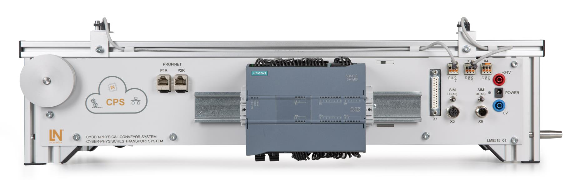
Siemens S7 1200 PLC with a signal board installed
DC motor (labeled
M1)Two magnetic field sensors (labeled
B1andB2)A PCB board that (re) wires the I/O of the PLC
A 20-pin connector to connect the PLC IO to additional sensors and actuators.
Depending on the revision, the board provides four or five sensor inputs (
X2,X3,X4,X5and an optionalX6)In addition there are one or two simulation switches (
SIM DI) for the sensorsX5andX6. The simulation switches simulate a sensor input, even though no sensor is connected to the sensor connector on the conveyor belt.The PLC has an analog input module, that is wired in a way to measure the PLC’s power consumption and input voltage.
A
Quick-Chart (in german), showing the conveyor’s IO is available.
Todo
Make yourself familiar with the conveyor belt and identify each of the inputs