2. Use Case Diagram
A use case describes the functionality of the software system that an actor must perform to obtain a desired result or to achieve a goal. Use cases should allow to talk to the future user about the functionality of the software system without getting lost in details right away.
An actor is a role played by a user of the software system. Actors can be humans or other automated systems. They are always external to the system.
A use case diagram gives a good overview of the software system and its interfaces to the environment at a high level of abstraction. The actors are often entered as stick figures, but can also be represented by a rectangle or pictogram (e.g., as a computer symbol).
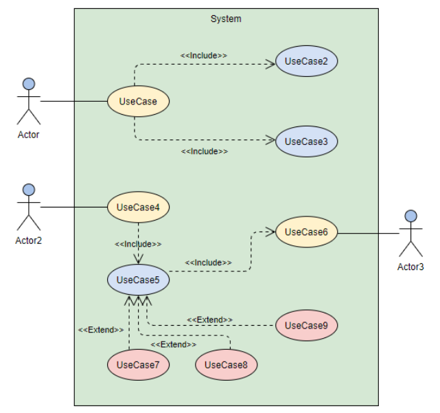
A line between actor and use case means that communication is taking place. The system under consideration is modeled as a large rectangle that includes all use cases.
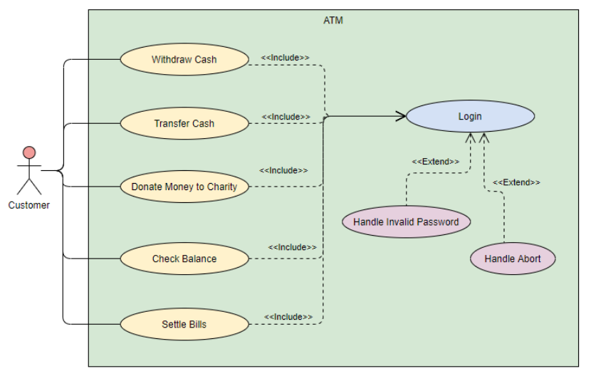
With the help of the extend relationship, a use case A is extended by a use case B. The use case A describes the basic functionality, the use case B specifies extensions. Use case A can be executed alone or together with the extensions. For an extension to be inserted, a condition must be met. This condition can be specified as a note or comment if required and appended to the extend relationship.
The include relationship allows the common functionality of use-cases A and B to be described by a use-case C. The use case C is not optional, but is always required for the correct execution of A and B. The include relationship eliminates the need to describe the same behavior multiple times. In contrast to the extend relationship, the execution of use case C is not dependent on any condition.
Use case diagrams are created per use case. A visual connection of multiple use cases is not typical, here individual diagrams are used.
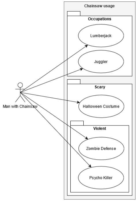
To represent boundaries, e.g. of devices, packages can be used.
Hint
Use case diagrams can be created online: https://app.diagrams.net/