Preparation: Logic Elements
The following section contain an introduction to the logic elements to create logic circuits. Please carefully execute the todos as this knowledge is required for the practical session.
Logic circuits
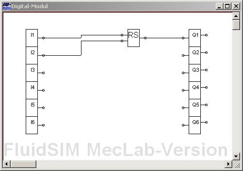
In FluidSIM®, logic modules can be used to control interactions, e.g. by relais. The digital module can be found in FluidSIM® in the components under the Digital Technology category. Place it in a new circuit; double-click on the placed digital module to open a window in which you can edit the functions of the digital module.
Todo
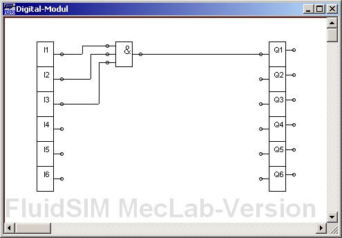
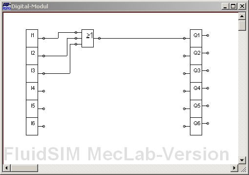
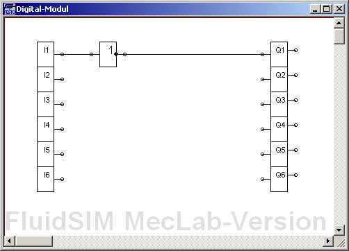
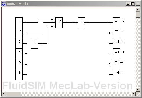
Transfer the following logic circuits into FluidSIM® and examine the behavior of the circuits by starting the simulation and setting the input channels I1 to I3 to the HIGH state by clicking on them.
Additionally, fill in the truth table for the inputs and the output Q1.
Flip-Flops
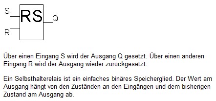
Holding elements - or flip-flops - are storing elements. The RS flip-flop is the simplest flip-flop. It has a set input and a reset input.
Flags: Often the results of logic operations depend on previous results. These results must be stored temporarily so that they can be used in the next cycle. Flags are used for this purpose.
Todo
Create the logic circuit shown below in FluidSIM®, test the behavior, and describe it. For which control task can the holding element (flip-flop) be used?
Todo
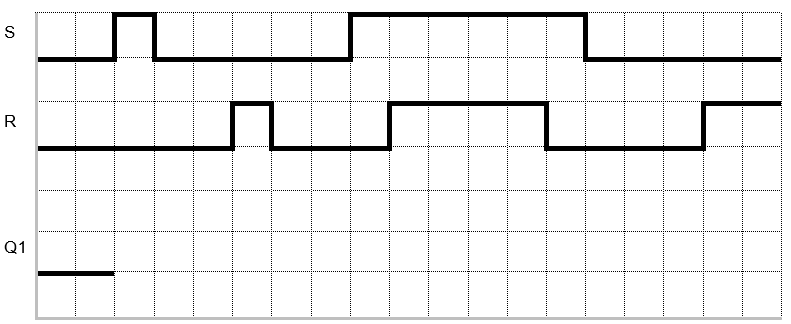
Plot the Q1 signal waveform on the timing diagram below.
Warning
Attention with FluidSIM: If both S and R are High, no dominance is set.
If both inputs are active, the state of the function block is undefined!
Warning
Depending on literature and PLC manufacturer, the RS and SR function blocks are partly defined differently. Attention: Only from the designation RS or SR one cannot find out whether the setting or the resetting is dominant!
Therefore we use the following notation for the lecture: The dominance is indicated by a “1” at the end of the input name.
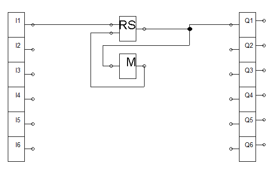
To couple an output signal back to an input, a memory element - a flag - is required. A flag stores the current value and passes it to the output in the next cycle.
Todo
Test the following circuit and create the timing diagram.
Bringing all together
Todo
Create the circuit shown below in FluidSIM®:
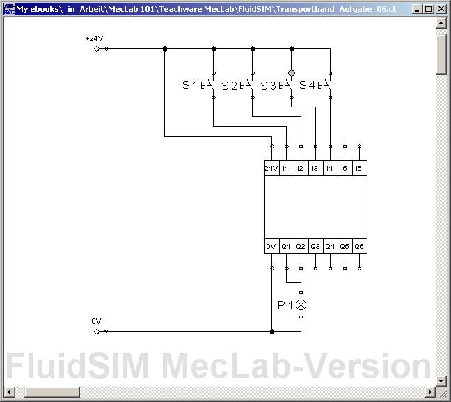
Todo
Open the logic module and create a program with the following properties:
The lamp P1 should light up when the buttons S1 and S2 have been pressed simultaneously; thus, light up after pushbuttons S1 and S2 have been released again.
The lamp should go out when pushbuttons S3 or S4 have been pressed.
Hint
A button can be pressed permanently by holding down the shift key while clicking.
Todo
Extend the circuit so that an electric motor is switched on and off in addition to the lamp. (Parallel connection!)