2. Assignment: Handling Station
Todo
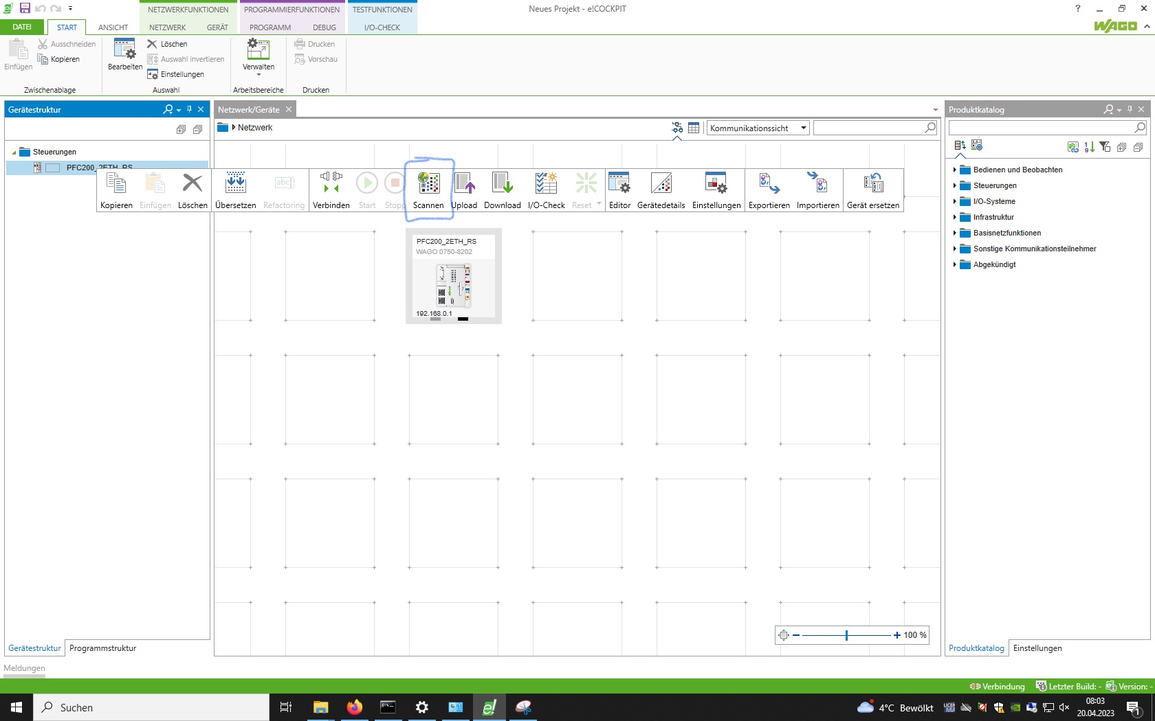
Scan for and connect to the PLC from inside e!Cockpit. This is how to do it:
Take a look at the PLC rack and read the PLC’s IP address. Then navigate to Network - Settings and put in the right IP range to scan. For example, scanning in the range from 192.168.1.1 till 192.168.1.254 will detect all PLC’s in this network that have IP addresses within that range. Please note that this scanning process can take multiple trials to detect the PLC. If a PLC is not detected immediately, scan again.
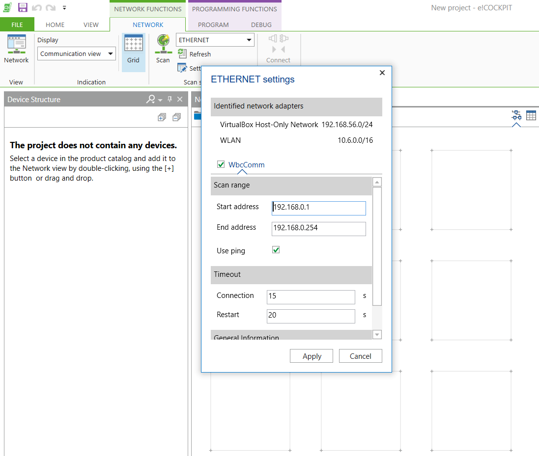
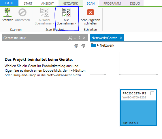
After detecting the PLC, click Apply All to add the PLC to your project
Hint
The IP address of the PLC used in this session is 192.168.0.1
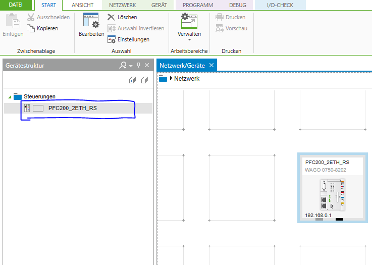
Note that now the PLC has been added to your project.
This has only added the PLC module itself. But the PLC has other modules attached to it that were not yet scanned for. Every module adds new functionality to the PLC. For example, module 750-430 is an 8-channel digital input card. Meaning that the wire-plugs on the 750-430 accept digital sensors like an inductive sensor, light beam sensor, etc.
If you are wondering what a certian module does, search its module number online.
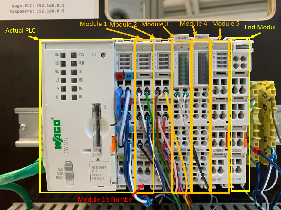
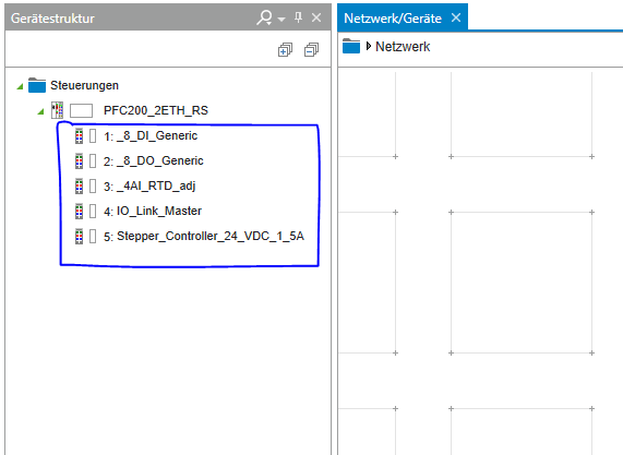
Fig. 2.3 The PLC in this session has 5 modules inserted between the PLC and the End Module. Note that the End Module has to always be there at the end.
Todo
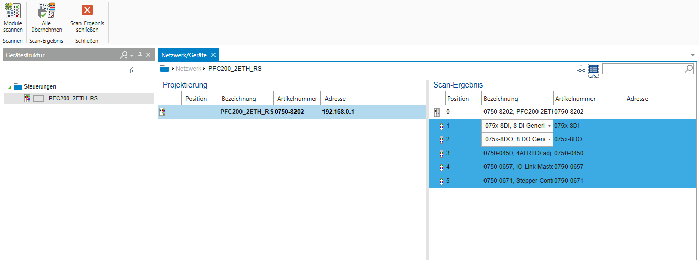
Right click on the newly added PLC and choose scan to scan for the modules inserted next to the PLC.
The scan results should identify 5 modules. Click add all to add all modules to the project
After adding all scanned modules, your device structure should look like this:
2.1. Signal Mapping
The PLC is wired to the conveyor belt’s components as follows:
Component |
Input address |
Output address |
|---|---|---|
1S1 |
%IX1.0 |
|
1S2 |
%IX1.1 |
|
2S1 |
%IX1.2 |
|
2S2 |
%IX1.3 |
|
1M1 |
%QX0.0 |
|
1M2 |
%QX0.1 |
|
2M1 |
%QX0.2 |
|
2M2 |
%QX0.3 |
|
3M1 |
%QX0.4 |
Todo
Navigate to Device Structure and give these inputs/outputs suitable names to be used in the program.
2.2. State Machine as Enumeration
State machines can be implemented as enumerations in ST. An enumeration is a user defined type that holds a specific number of elements. In the case of state machines, each enumeration element represents a state.
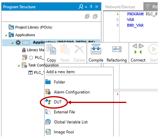
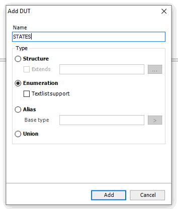
To create an enumeration in e!Cockpit, navigate to Program Structure in the bottom left corner, right click on Applicaition and
select DUT.
Todo
Create an enumeration and give it the name STATES.
Todo
Add one state element for each state you have in your state machine. Separate each state by a comma and name each state according to your state machine diagram
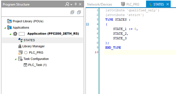
Fig. 2.4 Example of an enumeration with unspecific state names. Note: you have to give states meaningful names (e.g., MOTOR_FORWARD, MOTOR_BACKWARD, etc.) not call the states STATE_1, STATE_2, etc.
2.3. PLC_PRG and the Switch Case Statement
Todo
Create an instance of the STATES enumeration in you program (call it state) and an Entry boolean variable. Initialize your state variable with
the INIT state.
Note
Every state machine should include the INIT state. This is the first state the program should run when powered. If you didn’t
include an INIT state in your preparation, include one now.
PROGRAM PLC_PRG
VAR
        state : STATES := STATES.INIT;
        Entry : BOOL := TRUE;
END_VAR
Todo
In the program code window, write a switch-case statement to switch between your states. Use the Entry variable to
implement the entry code.
CASE state OF
        STATES.INIT:
                IF Entry THEN
                        Entry := FALSE;
                        // insert "entry" code here. This code will be carried out only once upon entry to the state.

                END_IF
                // insert "do" code here. This code will be carried out every PLC cycle while the program is in this state.

                //exit
                IF [exit_condition_here] THEN
                        Entry := TRUE;
                        state := STATES.[next_state_here];
                        // insert "exit" code here. This code will run only once upon exiting this state.

                END_IF;
        STATES.NEXT_STATE: // repeat the pattern above for every state.
        .
        .
        .
        .
        .
END_CASE
Danger
With the double acting cylinders, do not set both outlets as TRUE at the same time.
Whenever you set an outlet as TRUE, be sure to follow it with the reverse on the opposite outlet.
// retracts cylinder 1
b1M1 := FALSE;
b1M2 := NOT b1M1; // this makes sure that not both outlets are actuated

// extends cylinder 2
b2M1 := TRUE;
b2M2 := NOT b2M1;
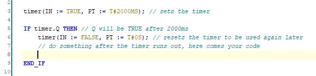
Hint
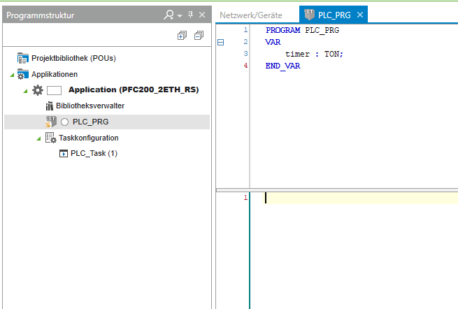
To use a timer, create a timer variable in PLC_PRG and call it anything, for example, timer. This variable is of data type TON. Give it no default value.
Your timer declaration may look like this:
When attempting to use the timer in the main program, you may see the following TON documentation.
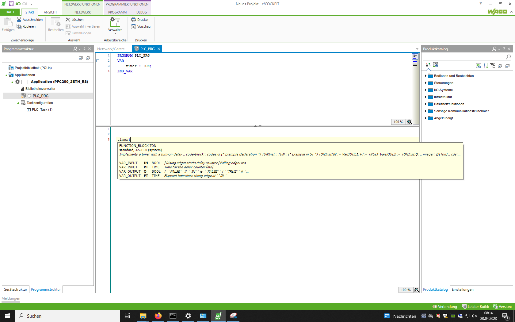
This timer function block (of type TON) accepts 2 inputs, namely IN and PT, and gives us 2 optional outputs, namely Q and ET.
Hint
IN sets the timer
PT gives the time value that the timer should count
Q is set to TRUE when the timer finishes counting
ET gives the elapsed time since IN was set to TRUE
To check if the timer has counted untill the end, check if timer.Q is TRUE. Do not forget to reset IN after the counter has finished counting, otherwise the counter wont be usable again.
Todo
After writing the program, connect the PLC to the station using the 15-pin plug attached to the PLC rack, upload the program to the PLC and test if it works as intented.
2.4. Visualization in e!Cockpit
In this section, a visualization of the program will be created. Visualization help show what is going on in the real machine at a glance.
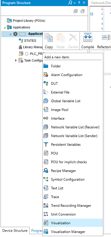
Todo
Right click on Applicaition and choose Visualization to add a visualization to your program.
Todo
Check Active on both available symbol libraries and click Add.
2.4.1. Changing colors
Todo
In the visualization window, drag and drop some basic shapes from the Visualization Toolbox on the left.
Try to draw a simple conveyor belt shape using the basic shapes. E.g., use lines for the belt and a circle for the workpiece, etc.
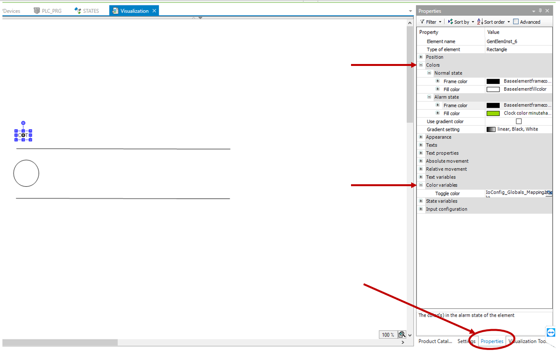
Variables can be assigned to shapes from within the Properties tab on the bottom left. E.g., variables can toggle a color change
of shapes or move the shapes along an axis in the visualization.
Todo
Drag and drop a simple rectangle. Assign the OPT sensor’s variable as the color variable. In Colors, make the rectangle
turn green when in alarm state. This makes the rectangle in the visualization turn green when the sensor is triggered.
Upload your new program and check if it works.
2.4.2. Showing current state
Todo
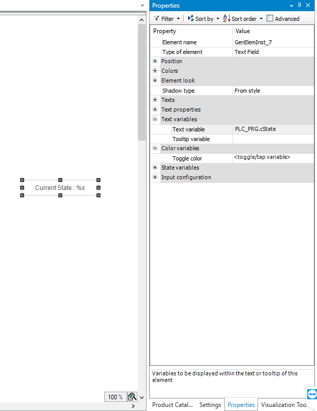
From the Common Controls tab, drag and drop a Text Field.
Text fields can show dynamic variables that change during runtime. This is done by using placeholders.
Todo
In your main program, create a new STRING type variable to store the current state’s name in. In every state’s do code, assign
the current state’s name to that variable. In the visualization, show that variable by typing Current State : %s into a text field.
In that text field’s properties tab, link your newly created STRING variable as the Text variable. Run the program and see if the
current state is showed in the visualization.
Note
The placeholder %s is used to hold a string type variable. A list of placeholders can be found here.
2.4.3. Moving an object
An object’s position in the visualization can be coupled on an INT type variable from the program. This is done in Properties under
Absolute movement, Movement, and either X or Y for the corresponding axis.
Todo
Create a moving rectanle (represents the pneumatic cylinder) that moves when the real cylinder moves. Use a new INT type variable as your Absolute movement in X direction variable
and a new TON type variable to increment it. Adjust the incrementation size and delay for a better visualization.
2.4.4. Final task
Todo
Put everything together to build a visualization of the handling station. Show the current state as well as whether sensors are triggered or not (over color change). Moving parts should also move in the visualization. Use a button in the visualization to start the entire process.
Note
You can use parameters to show/hide objects in the visualization.