5. Electrical and Controller Properties
- The components inside Bittle are:
the main board on the top which is covered with a plastic shell.
the servos which are installed at every joint. (The motor shaft depicts joints and the motor body is connected to the limb)
the battery which is installed at the bottom.
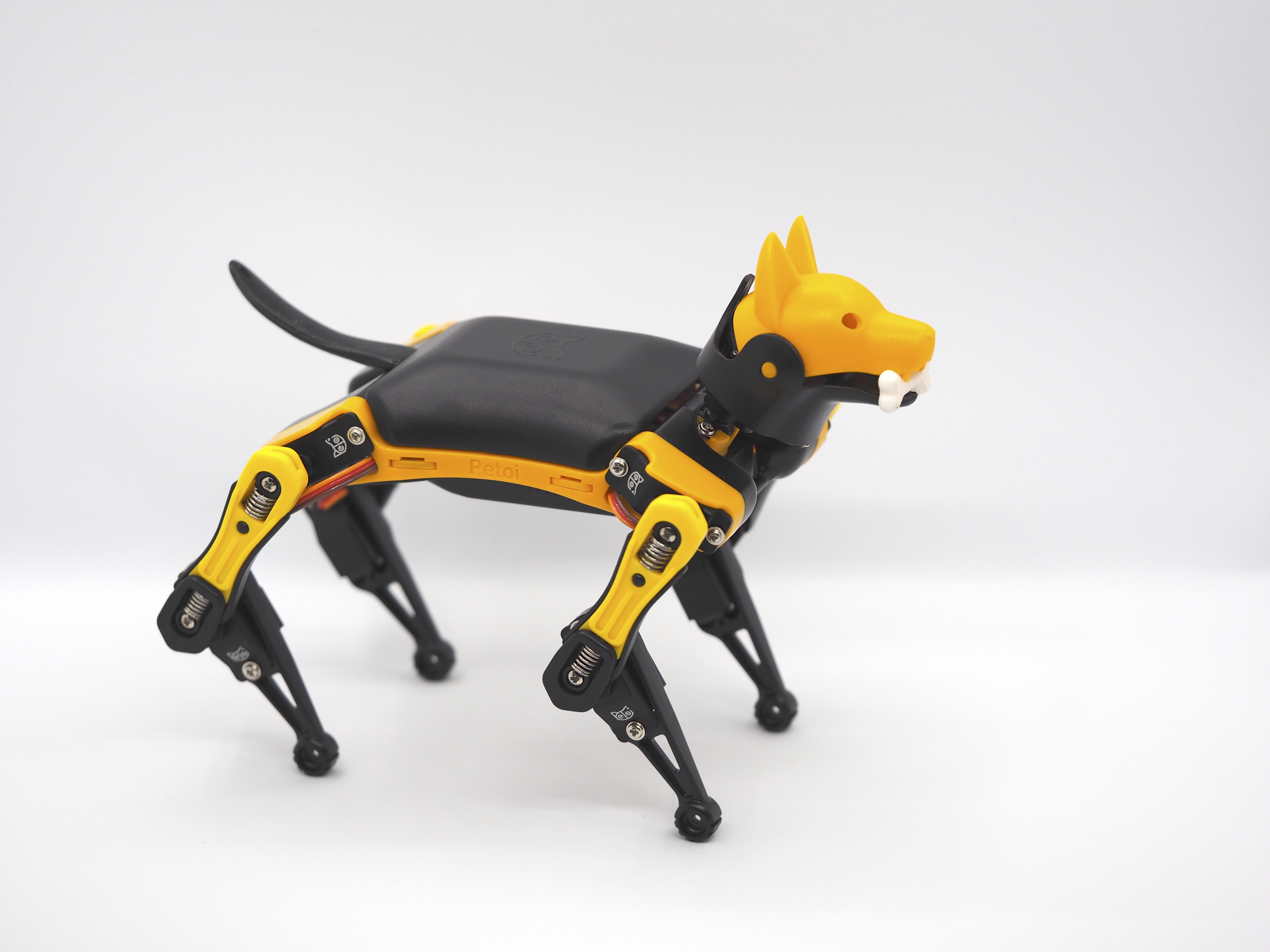
Fig. 5.1 Standing dog
Todo
Get familiar with the provided hardware.
5.1. Main Board
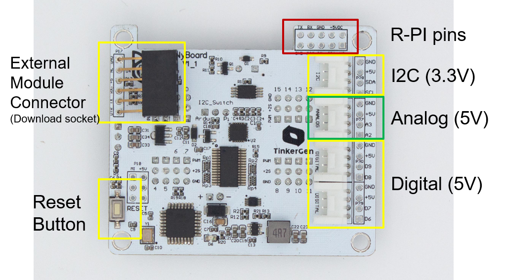
Fig. 5.2 Top view of main board
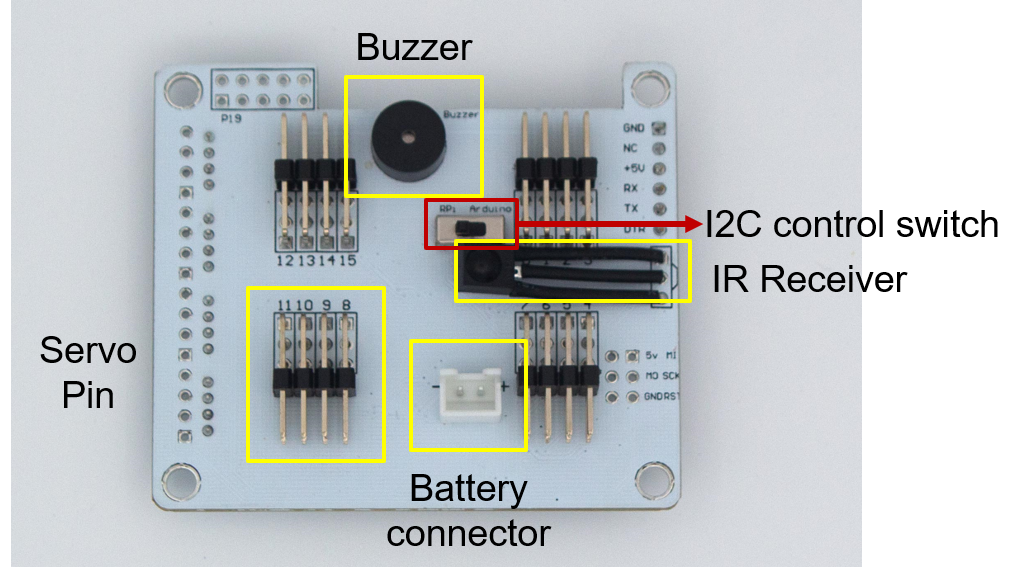
Fig. 5.3 Bottom view of main board
5.1.1. Specifications
Controller Specifications:
Mainboard Name
NyBoard V1_1
Microcontroller
ATmega328P
Operating Voltage
5V
Chip frequency / Clock speed
16 MHz
DC Current per I/O Pin
20mA
Memory usage:
Flash
32KB
SRAM
2KB
EEPROM
1KB
EEPROM (I2C)
8KB
- External Interface:
UART
I2C (TWI)
SPI
Additional on board components:
Component
Description
Protocol
Address / Pin
MPU6050
6 axis IMU
I2C
At 0x68
Interrupt pin
D2
PCA9685
16 channel PWM controller
I2C
At 0x40
AT24C64
EEPROM 8KB
I2C
At 0x54
VS1838B
IR Receiver
D4
Buzzer
D5
Voltage divider
A7
G1
External I2C
I2C
G2
External analog pins
Analog
A2, A3
G3
External digital pins
Digital
D8, D9
G4
External digital pins
Digital
D6, D7
LED
Single Green LED
Digital
D10
5.1.2. Board interface
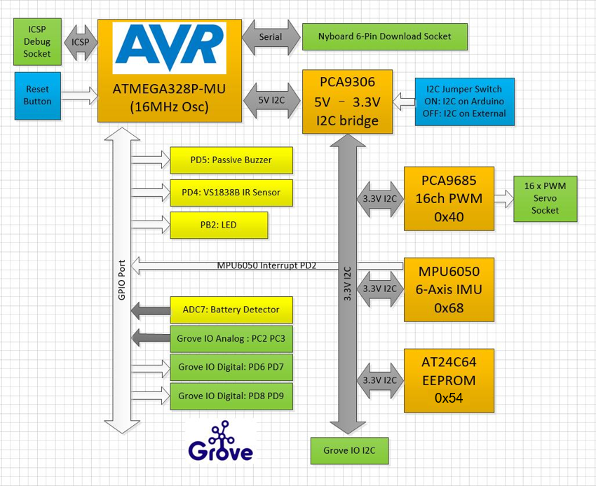
Fig. 5.4 Interface diagram

Fig. 5.5 Motor connection layout
5.1.3. Board power supply
The actual voltage is approximately 2x of the reading. A safe range of battery voltage is below 10V. You should charge the battery in time when the battery is lower than 7.4V.

The main chips are powered by a Low-dropout (LDO) linear regulator for noise removal and better stability. LM1117-5V and XC6206P-3.3V are used to power 5V and 3.3V chips. The 3.3V LDO is connected in serial after the 5V LDO for better efficiency.
There’s a diode between the battery and LM1117-5V to prevent damage by the wrong connection. There’s a self-recover fuse (6V 500mA) on the USB uploader to limit the current and protect the USB port.
The Raspberry Pi consumes much more power, so we choose TPS565201 DC-DC to provide a 5V 3A output. The peak output can be 5A and with high-temperature/current/voltage protection. It will cut off the power when the chip keeps outputting >4A and over 100 Celcius degrees until the temperature drops to normal.
The servos are powered by 2S Li-ion batteries directly. Pay attention not to short connect the power or any pins on the NyBoard.
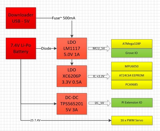
Fig. 5.6 Power supply diagram
5.2. Servos
The servos are used to execute the robot movements. These can be turned to the required angle as they have a built-in feedback circuit. Inside a servo motor, there is an electric motor which is in connected to a potentiometer using gear train. The potentiometer is used to measure the angle of rotation of the motor shaft. The wiring of almost all servos include VCC, GND and PWM input. PWM or Pulse width modulation is used to control the motor to the specific angle.
The controller controlling the servo sends pulse signal with duty cycle which nominally ranges between 1ms to 2 ms. For example, if at 1ms the motor turns to -90° and at 2ms the motor turns at +90°, then at 1.5 ms the motor will turn at 0°.

Fig. 5.7 Servo motor
5.3. Battery
Specifications of battery:
Battery type
Lithium Polymer
Number of cells
2 of 1000mAh
Total capacity
7.4Wh
Max discharge current
5A
Max output voltage
7.4V
Max recharge current
1A
Max recharge voltage
5V
Charging cable type
micro-USB
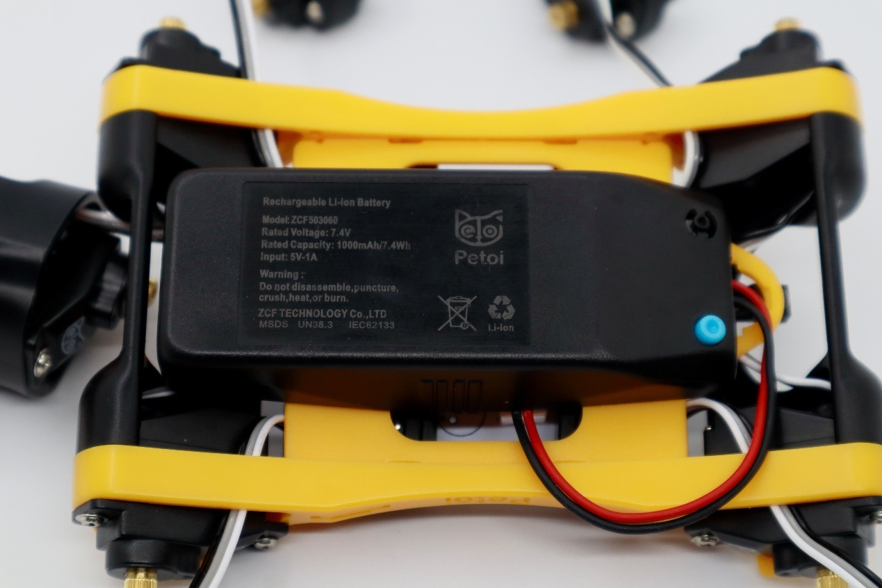
Fig. 5.8 Battery location and status LED.
5.3.1. Battery Status
Battery status LED color when Bittle is running or idle.
Blue
Charged
Red
Discharged
Charging status:
Battery status LED color when Bittle is charging.
Green
Charged
Red
Charging