8. Extensible Modules
8.1. Sensors and Actuators
The head of Bittle is designed to be a clip to hold extensible modules. Mentioned below are some popular modules. You can also wire other add-ons thanks to the rich contents of the Arduino and Raspberry Pi community.
You can find the demo codes of these modules in our GitHub repository. The codes can be found under ModuleTests folder inside the source code.
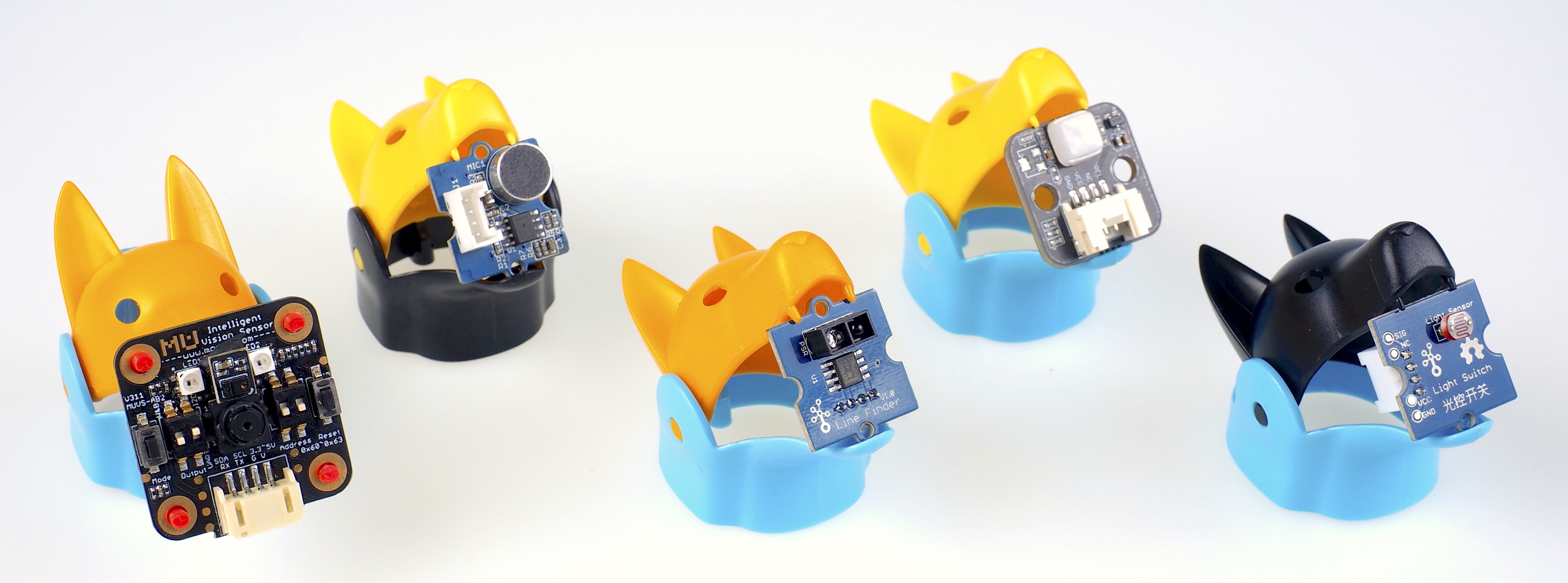
Fig. 8.7 Extensible Modules
- The modules are:
LEDs
Sound Sensor / Noise Detector
Light Sensor / Phototransistor
Touch Sensor
Infrared Reflective Sensor
PIR Sensor
OLED Display
Ultrasonic Sensor / Distance Sensor
8.2. Communication Modules
The Nyboard V1 used by robot uses the Atmel ATMEGA328P controller, which only supports only one serial port.The default serial baud rate is 115200bps. Pin definitions are shown in the table below:
Pin No. |
Name |
Usage |
1 |
DTR |
Modem signal DTR, reset NyBoard after serial download finished. |
2 |
RX |
ATMEGA328P RX (receive) |
3 |
TX |
ATMEGA328P TX (send) |
4 |
5V |
5V power for MCU and chips |
5 |
GND |
Ground |
6 |
GND |
Ground |
8.2.1. USB Adaptor
The module uses a CH340C USB bridge. The uploader has three LEDs: power, Tx, and Rx. Right after the connection, the Tx and Rx should blink for one second indicating initial communication, then dim. Only the power indicator LED should keep lighting up.
NyBoard download interface: used to connect to NyBoard, download program firmware to the robot, and communicate with the computer via serial port.
Communication module debugging interface: used to connect the Bluetooth or WiFi module, update the module program and debug the parameters. In order to avoid the cumbersome operation when connecting with Dupont wires, the pin ordering is slightly different from the NyBoard download interface - the TX/RX interface is reversed, and a GND pin becomes an RTS pin. For details on how to use the debugging interface of the communication module, see the following chapters.
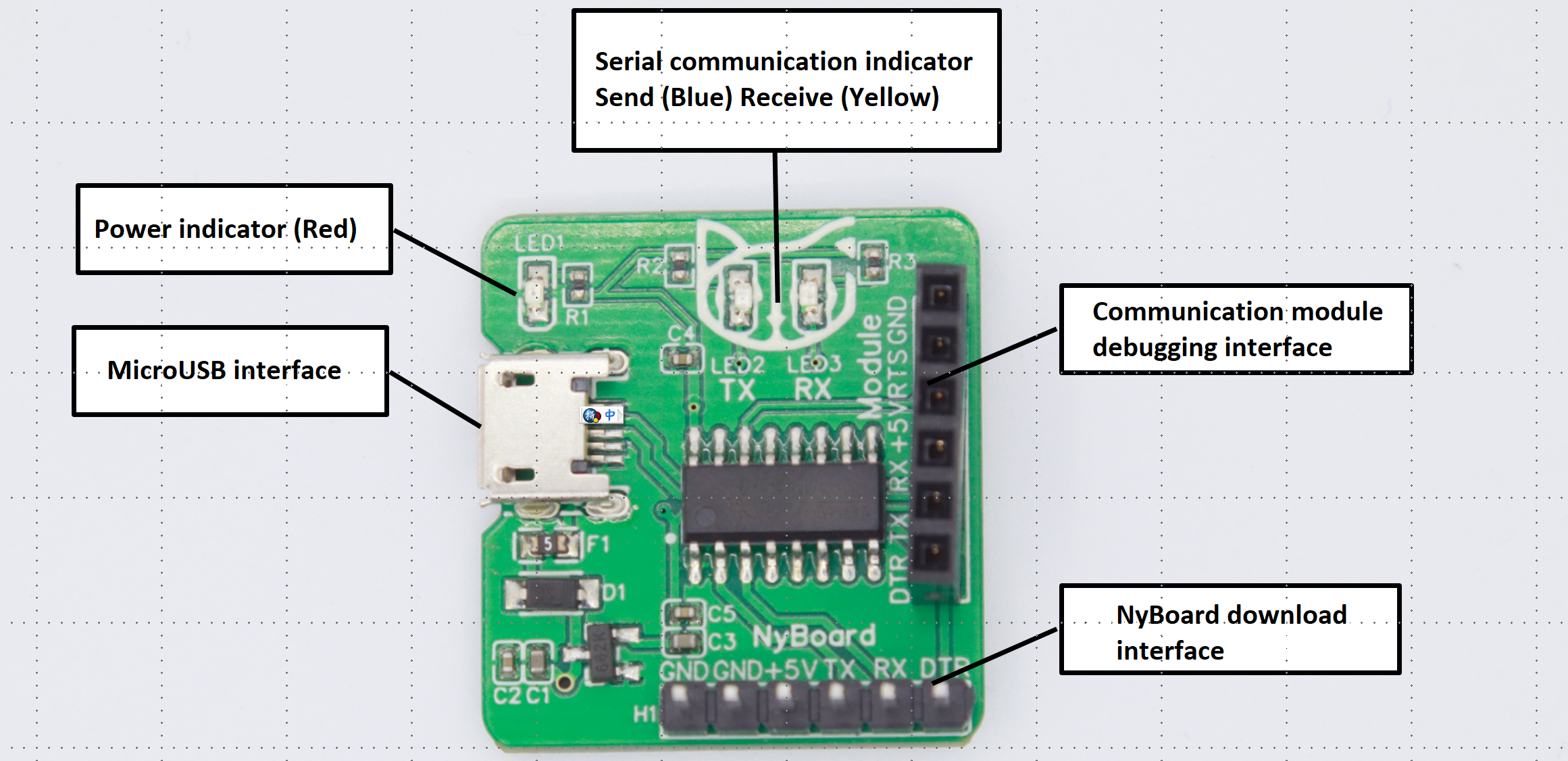
Fig. 8.8 USB Adapter Description
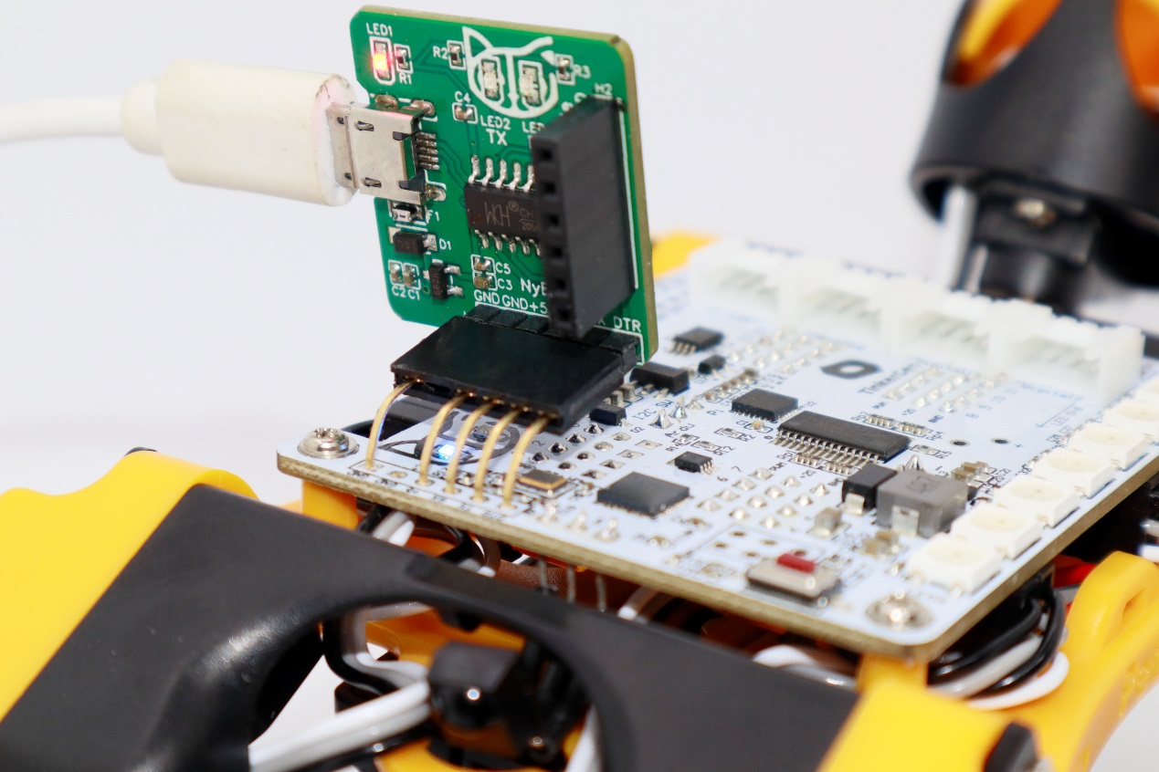
Fig. 8.9 USB Adapter Connection
Danger
Do not plug the NyBoard and the other module(WiFi or bluetooth) at the same time!
Warning
If Tx and Rx keep lighting up, there’s something wrong with the USB communication. Please check the Adaptor and USB cable.
8.2.2. Bluetooth Adaptor
The module uses JDY-23 Bluetooth 5.0 BLE module. It acts as a bridge between Bluetooth devices and micro-controllers. You can wirelessly upload firmware or control the motion of the robot through a Bluetooth connection. This module is also required to connect with the PETOI mobile app. A blinking LED on the Bluetooth module indicates waiting for a connection. If required, the default PIN for pairing is “0000“ or “1234”. After the pairing is successful, the system will assign a serial port name.
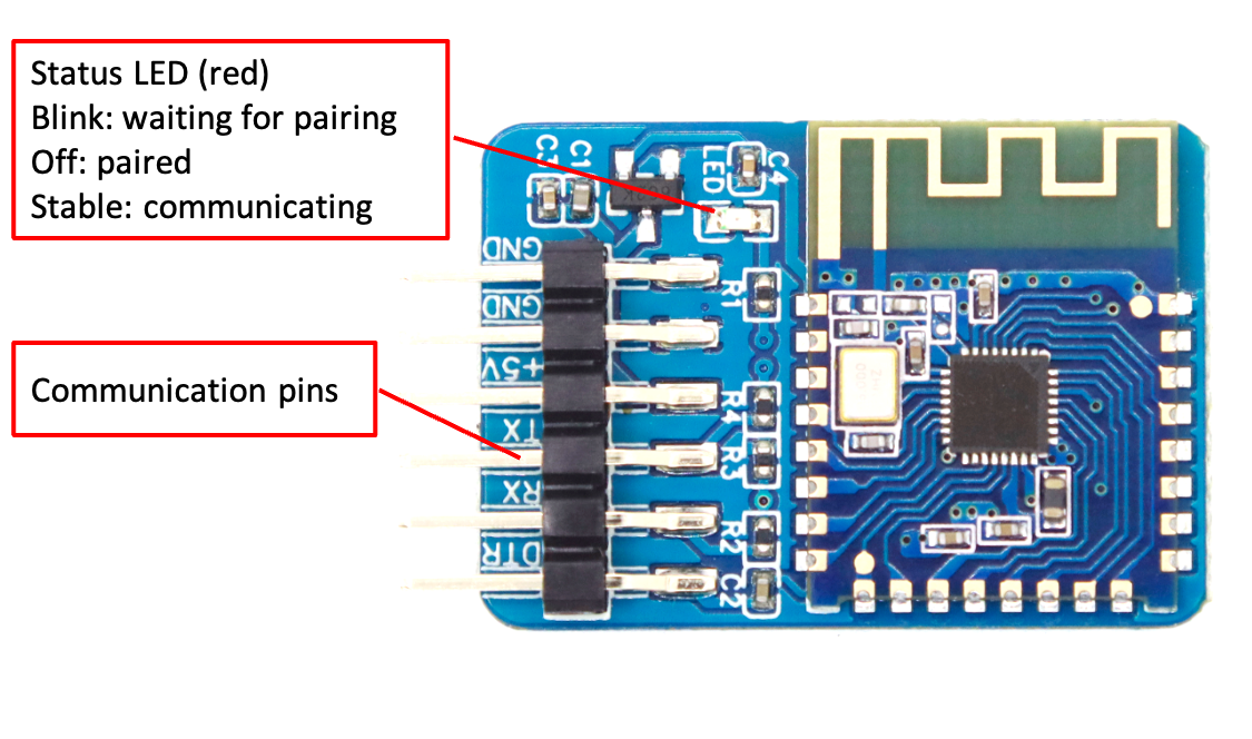
Fig. 8.10 Bluetooth Adapter Description
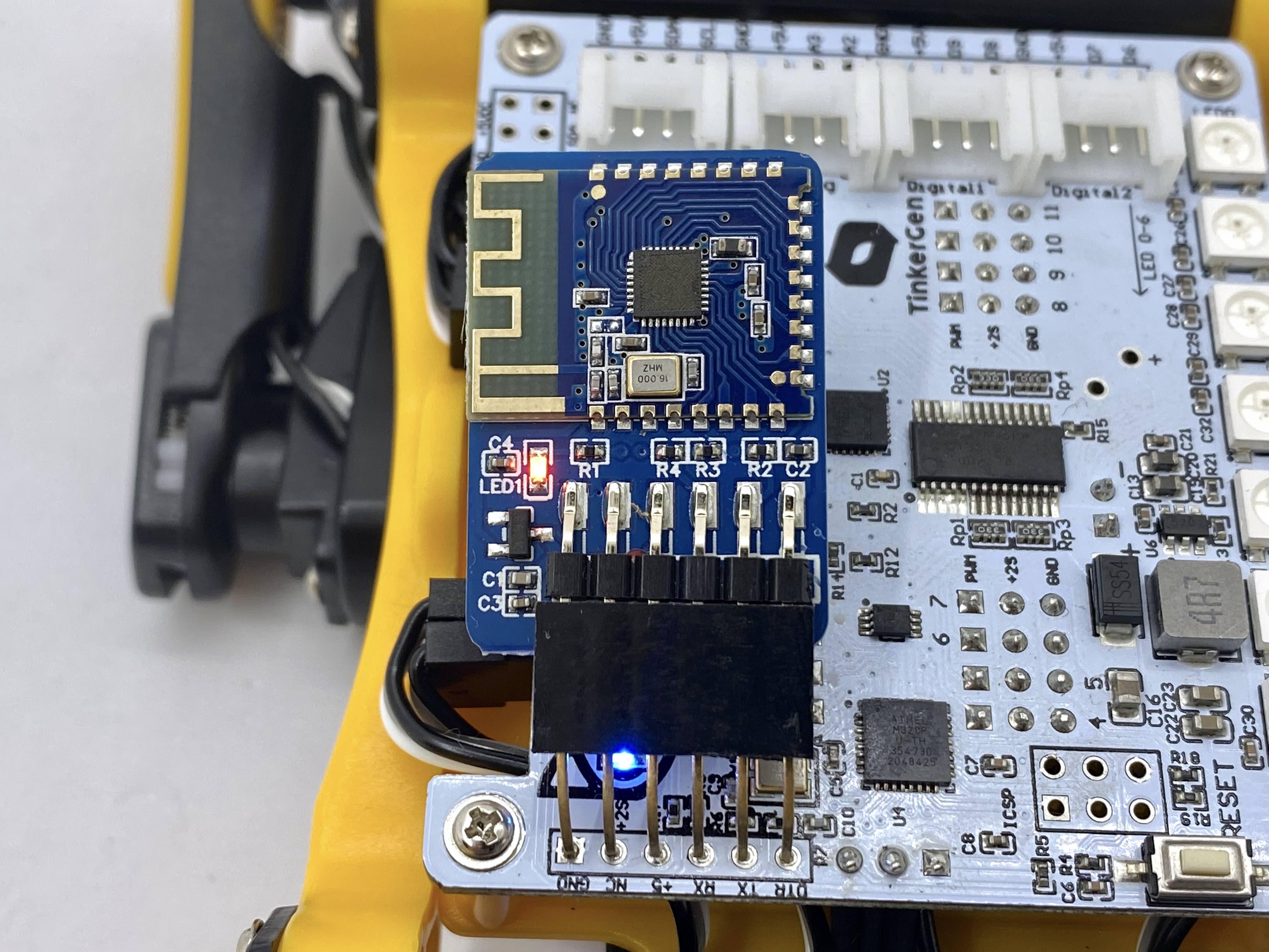
Fig. 8.11 Bluetooth Adapter Connection
To externally configure bluetooth adaptor, you can connect the Bluetooth Adaptor with USB Adaptor. To configure the module, use serial monitor with line ending as NL and CR and baud rate as 115200. The commonly used AT commands are given below, for complete list please refer JDY-23’s specification sheet.
Usage
Command
Check BT module version
AT+VER
Check BT broadcast name
AT+NAME
Change BT broadcast name
AT+NAME<Device Name>
Check serial baud rate
AT+BAUD
Change serial baud rate
AT+BAUD<Baud Rate Identifier>
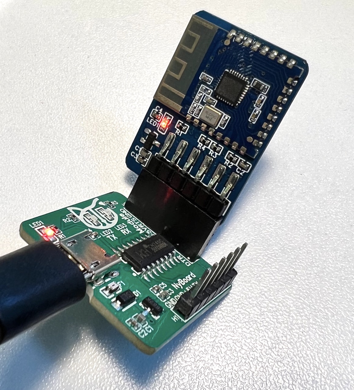
Fig. 8.12 Bluetooth - USB Configure
8.2.3. WiFi Adaptor
The module uses ESP8266EX’s official model ESP-WROOM-02D, 4MB QSPI Flash. The module includes an automatic download circuit and a communication module. The automatic download circuit refers to the official recommendation to use 2 S8050 transistors to receive the RTS and DTR signals from the CH340C downloader and trigger the download sequence.
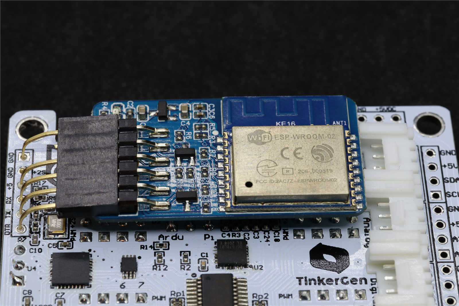
Fig. 8.13 Bluetooth Adapter Connection
- To setup the environment for WiFi adaptor, follow the steps below:
In Arduino IDE, open File -> Preferences.
Paste http://arduino.esp8266.com/stable/package_esp8266com_index.json in Additional Boards Manager URL’s section. Click OK and close Preferences Pop-up.
Open Board Manager from Tools -> Board -> Board Manager
Enter ESP8266 in the search bar in Board Manager. You will find a search result developed by ESP8266 Community.
Click on Install. Wait until it finishes.
Once done, select Generic ESP8266 Module from Tools -> Board -> ESP8266 Boards
Select the following settings in Tools menu.
Parameters
Settings
Builtin Led
2
Upload Speed
921600
CPU Frequency
80 MHz
Crystal Frequency
26 Mhz
Flash Frequency
40 Mhz
Flash Size
4MB (FS:2MB / OTA:1019KB
Reset Method
DTR reset
lwIP variant
V2 Lower memory
Erase Flash
Only sketch
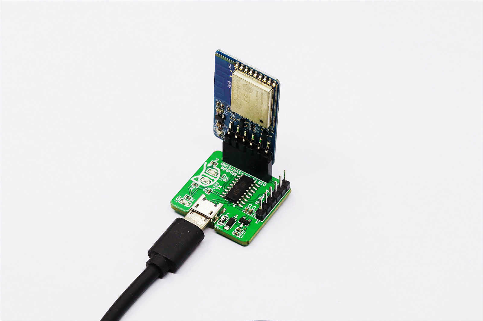
Fig. 8.14 ESP8266 - USB Configure
- To use the module, a sample code is available under OpenCat/ModuleTests/ESP8266WiFiController. The code folder consists of 3 files:
ESP8266WiFiController.ino: Arduino sketch with server core code.
mainpage.h: welcome page (html) in a char array.
actionpage.h: action controller page (html) in a char array.
- Steps to use sample code:
Open code with IDE. Set the parameters for ESP9266 as given above. Connect the ESP8266 to USB Module.
Upload the code. Open Serial Monitor and set line ending to NL and CR and baud rate as 115200.
The module will create a Access Point. Using a WiFi enabled device (Mobile, Tablet, PC etc.), connect to the access point named Bittle-AP.
Once WiFi is connected, open a web browser and enter 192.168.4.1 in address bar and go to it.
Here, configure your WiFi so that this ESP8266 can connect to it and thus to Internet.
After the WiFi connection between your router and ESP8266 is successful, the AP mode will switch to client mode and now your ESP8266 can connect to Internet.
Enter the IP address shown on Serial Monitor in address bar of your WiFi device. A webpage with various options will open. From here you can control your robot over WiFi.
Additional information about this is provided in a separate section to keep this short. You can read about it here Controlling Bittle (Advanced).
8.3. Imaging Module
In addition to above mentioned modules, you can use a Camera module with Bittle to see what your robot dog is seeing.
For this, an ESP32 Camera module is suitable.
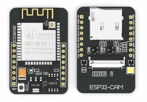
Fig. 8.15 ESP32 Cam Board layout (ref: https://docs.ai-thinker.com/en/esp32-cam)
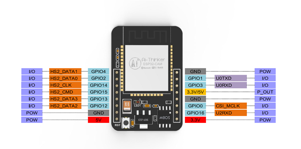
Fig. 8.16 ESP32 Cam Pinouts (ref: https://docs.ai-thinker.com/en/esp32-cam)
- To setup the environment for ESP32 Camera, follow the steps below:
In Arduino IDE, open File -> Preferences.
Paste https://raw.githubusercontent.com/espressif/arduino-esp32/gh-pages/package_esp32_index.json in Additional Boards Manager URL’s section. Click OK and close Preferences Pop-up.
Open Board Manager from Tools -> Board -> Board Manager
Enter ESP32 in the search bar in Board Manager. You will find a search result developed by esp32.
Click on Install. Wait until it finishes.
Once done, select AI Thinker ESP32-CAM from Tools -> Board -> ESP32 Arduino
Select the following settings in Tools menu.
Parameters
Settings
Partition Scheme
Huge APP
Pin Connection with USB Adapter
ESP 32 Cam
USB Adaptor
5V
5V
GND
GND
UnR
TX
UnT
RX
IO0
GND (when uploading)
- Steps to use sample code:
Open code with IDE. Open Example file named CameraWebServer from File -> Examples -> ESP32 -> Camera -> CameraWebServer
Set the credentials for your WiFi, (SSID and Password)
Please confirm that CAMERA_MODEL_AI_THINKER is selected in the code as this is our board.
Connect the ESP32_Cam module with the FTDI programmer if not already done. Connect the complete setup to PC using USB cable.
Select correct COM port and Upload the code. While uploading, keep in mind that GPIO 0 has to connect to GND and module has to reset to go in download mode before you upload code to it.
After successful upload, disconnect GPIO 0 from GND.
Open Serial Monitor. Set the Baud Rate to 115200.
Note the IP-Address and open it in a browser.
Use onscreen options to control the camera and adjust its parameters.
Note
To use Flash / On board LED, please refer the in lecture presentation for code snippets.
Note
If the upload fails, check in serial monitor if your esp32cam is in download mode (baud rate: 115200).
If it is in download mode, upload again and when you see dots (…) in output window, press reset button on esp32cam.
If you face problems for more than 30 minutes, contact your instructor.