14. Problem Solving
14.1. Buzzer Sounds
The robot will keep pausing its movements with beeping sounds when the battery is low. The battery needs to be charged using a a 5V micro-USB cable. Considering safety, the battery won’t supply power during charging.
Buzzer sound meaning:
Sound type |
Occasion |
Explanation |
Short melody |
Power on or reboot |
The program starts successfully |
Short beep |
During use |
The program receives a command |
Repetitive melody |
During use and pausing the movements |
The battery is low or unconnected |
14.2. Download Base Firmware
The OpenCat repository consists of various codes from module test to base firmware.
Warning
After downloading Please DO NOT modify any file until specifically mentioned in the tutorial.
- To begin with download,
Copy the link and open it in a browser, the download should start automatically -> https://github.com/PetoiCamp/OpenCat/archive/61fb3efe670c947791739dba86d87118f6021bb8.zip
Extract the files and rename the folder to OpenCat. Please check that the files are in following structure /OpenCat/OpenCat.ino
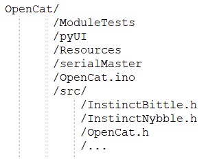
Fig. 14.1 Required file structure
14.3. Install Base Firmware
If in case you are unable to configure your device or its not functioning as intended, try installing the firmware again.
Warning
Before proceeding, please confirm that all wire connections are OK and your code is error free.
If the problem is in your code, the base firmware won’t be able to fix it.
- Follow the steps below to install base firmware:
Open Arduino IDE / Platform IO.
Open OpenCat.ino inside your IDE.
In the code, select your robot and board version. Uncomment the required lines by removing // and keep the rest of the code as it is.
Comment out #define MAIN_SKETCH (if you want to configure your board) by adding // in front of the line.
Set the Board configurations in IDE (Tools-> Board) to Arduino UNO and select the correct COM port.
Upload the code and open serial monitor.
Wait until you see Ready on serial monitor.
If your calibration is successful, Uncomment #define MAIN_SKETCH to make it active. Upload the code again after that.
14.4. Problem Loading Base Firmware
There can be multiple reasons for this, but the most common is incorrect file structure. This file corresponds to the source code downloaded from the link provided. Please consider checking the file structure and comparing it with the structure provided in Download Base Firmware.
14.5. Problem Uploading Program
Please check if the I2C switch on the main board is in correct mode. The I2C switch changes the master of I2C devices (gyro/accelerometer, servo driver, external EEPROM). On default “Arduino”, NyBoard uses the onboard ATmega328P as the master chip. On “RPi”, NyBoard uses external chips connected through the I2C ports (SDA, SCL) as the master chip.
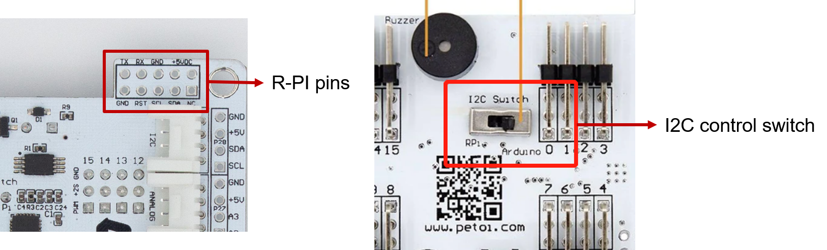
Fig. 14.2 I2C switch
14.6. Problem with Device COM Port
If you cannot find the port for your device on IDE, check the device manager if your device is connected properly and you have the required device driver installed.
The driver required is CH340. You can download it from here -> http://www.wch-ic.com/downloads/CH341SER_ZIP.html
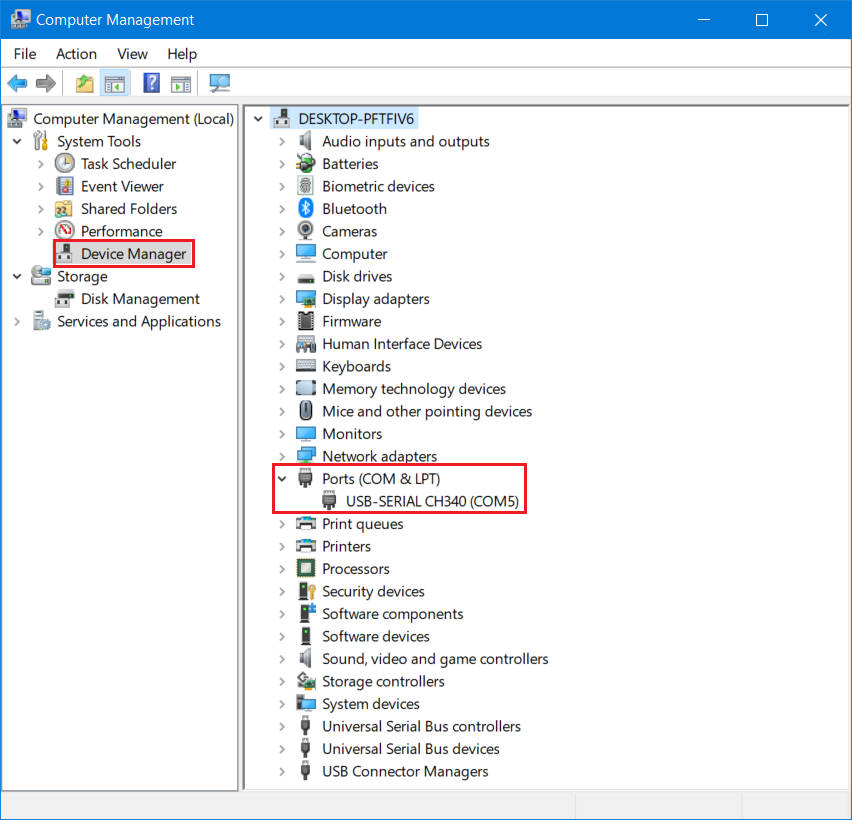
Fig. 14.3 Device manager
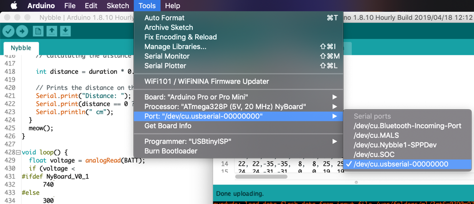
Fig. 14.4 Port selection in IDE
14.7. Problem with Serial Port Permission
If you are using LINUX system and have issues uploading or connecting to COM port, please follow the instructions mentioned here -> https://playground.arduino.cc/Linux/All/#Permission
14.8. Individual Module Test
You can test individual modules of the robot by uploading the codes available under the folder ModuleTests. To do do, open the .ino file from the required test module folder and upload the code by keeping the board setting mentioned earlier.
It is suggested to begin the module test with testBuzzer.ino code.
14.9. Problem with Python Packages
The Terminal is a built-in interface on Mac or Linux machines. The equivalent environment on Windows machines is called the Command-Line Tool (CMD). It’s recommended that you install Anaconda to manage your Python environment. It can also provide the Powershell as a Terminal for older Windows machines.
The python scripts work on Python V3. Install pip if not already installed -> https://pip.pypa.io/en/stable/installation/
- Install the following packages using pip:
pyserial
pillow
pip3 install pyserial pillow
- To run the code:
In the Terminal, use the cd command to navigate to the OpenCat/pyUI/ folder. You can use the Tab key to auto-complete the path name.
After entering the pyUI/ folder, enter ls and ensure you can see the UI.py and other python source codes listed.
Enter python3 UI.py.
14.10. Problem Uploading on ESP32 Camera
- There are few things to check:
Correct hardware board selected in Tools menu
GPIO 0 is set to GND when uploading. Reset once after doing that to enable download mode.
Hardware is 5V compatible. Try switching to 5V input from FTDI programmer.
Brownout detector was triggered? Include these header files:
#include "soc/soc.h" //disable brownout problems
#include "soc/rtc_cntl_reg.h"  //disable brownout problems
Include this inside setup()
WRITE_PERI_REG(RTC_CNTL_BROWN_OUT_REG, 0); //disable brownout detector
If you have other issues, check the following link ( https://randomnerdtutorials.com/esp32-cam-troubleshooting-guide/ )
You can also use Arduino UNO to upload code to your ESp32 CAM module.
Connect the following pins:
ESP32 CAM
Arduino UNO
5V
5V
GND
GND
UnT
Tx (PIN 1)
UnR
Rx (PIN 0)
IO0
GND (when uploading)
- Steps to use sample code:
Upload BareMinimun code to your UNO.
Select the following settings in Tools menu.
Parameters
Settings
Board
ESP32 Wrover Module
Upload Speed
115200
Flash Frequency
40 Mhz
Partition Scheme
Huge APP
Now you can upload your code to your esp32cam.