11. Teach Bittle New Skills
11.1. Understand skills in InstinctBittle.h.
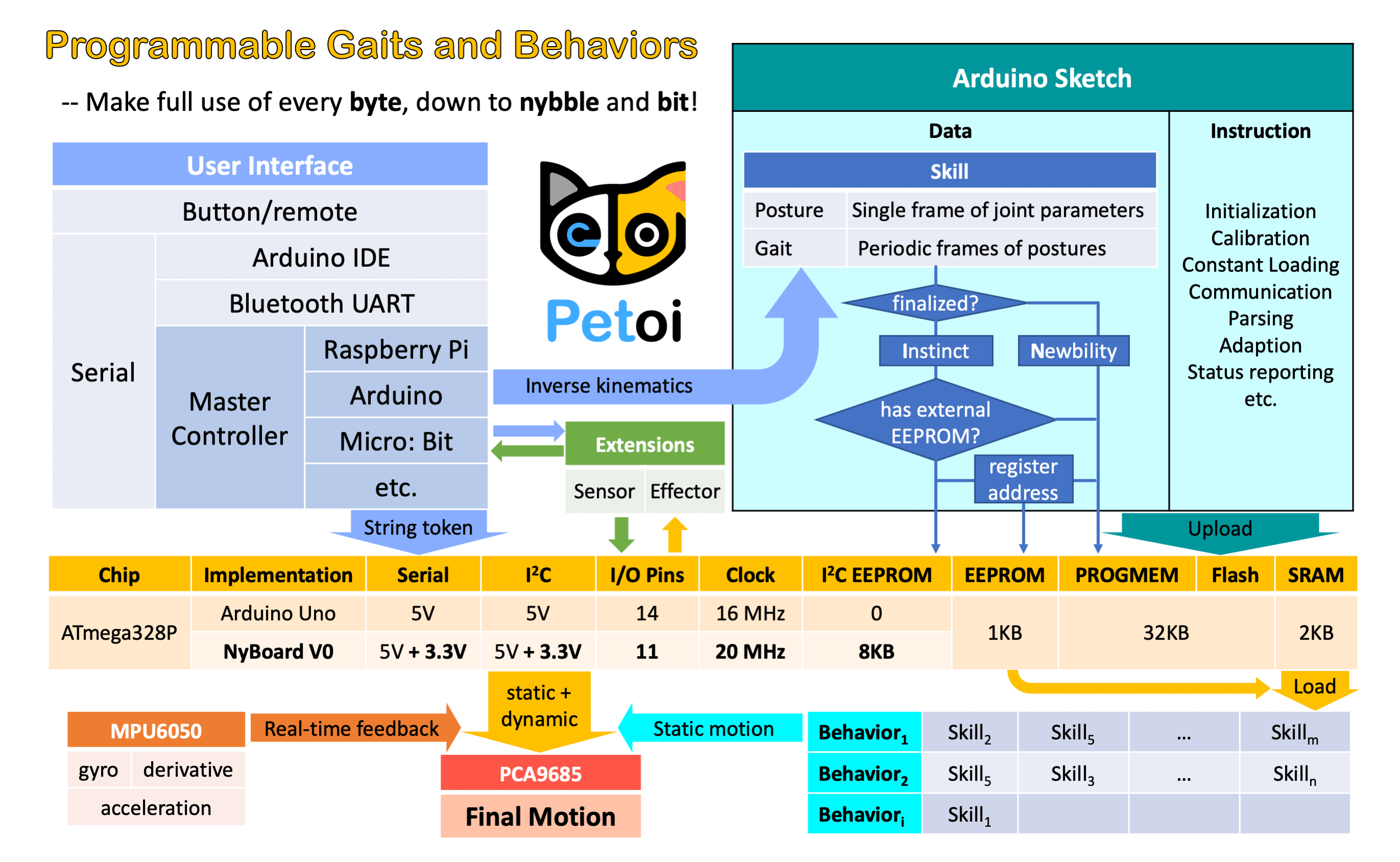
Fig. 11.1 Bittle Instinct Summary
EEPROM has limited (1,000,000) write cycles. So I want to minimize the write operations on it.
There are two kinds of skills: Instincts and Newbility. The addresses of both are written to the onboard EEPROM(1KB) as a lookup table, but the actual data is stored at different memory locations:
I2C EEPROM (8KB) stores Instincts.
The Instincts are already fine-tuned/fixed skills. You can compare them to “muscle memory”. Multiple Instincts are linearly written to the I2C EEPROM only once with WriteInstinct.ino. Their addresses are generated and saved to the lookup table in onboard EEPROM during the runtime of WriteInstinct.ino.
PROGMEM (sharing the 32KB flash with the sketch) stores Newbility.
A Newbility is any new experimental skill that requires a lot of tests. It’s not written to the I2C nor onboard EEPROM, but the flash memory in the format of PROGMEM. It has to be uploaded as one part of the Arduino sketch. Its address is also assigned during the runtime of the code, though the value rarely changes if the total number of skills (including all Instincts and Newbilities) is unchanged.
11.2. Example InstinctBittle.h
//a short version of InstinctBittle.h as example

#define BITTLE
#define NUM_SKILLS 4
#define I2C_EEPROM

const char rest[] PROGMEM = {
1, 0, 0, 1,
-30, -80, -45,   0,  -3,  -3,   3,   3,  75,  75,  75,  75, -55, -55, -55, -55,};
const char zero[] PROGMEM = {
1, 0, 0, 1,
    0,   0,   0,   0,   0,   0,   0,   0,   0,   0,   0,   0,   0,   0,   0,   0,};

const char crF[] PROGMEM = {
36, 0, -3, 1,
61,  68,  54,  61, -26, -39, -13, -26,
66,  61,  58,  55, -26, -39, -13, -26,
...
51,  81,  45,  72, -25, -37, -12, -25,
55,  76,  49,  68, -26, -38, -13, -26,
60,  70,  53,  62, -26, -39, -13, -26,
};

const char pu[] PROGMEM = {
-8, 0, -15, 1,
6, 7, 3,
0,   0,   0,   0,   0,   0,   0,   0,  30,  30,  30,  30,  30,  30,  30,  30,        5, 0,
15,  0,   0,   0,   0,   0,   0,   0,  30,  35,  40,  29,  50,  15,  15,  15,        5, 0,
30,  0,   0,   0,   0,   0,   0,   0,  27,  35,  40,  60,  50,  15,  20,  45,        5, 0,
15,  0,   0,   0,   0,   0,   0,   0,  45,  35,  40,  60,  25,  20,  20,  60,        5, 0,
0,   0,   0,   0,   0,   0,   0,   0,  50,  35,  75,  60,  20,  30,  20,  60,        6, 0,
-15, 0,   0,   0,   0,   0,   0,   0,  60,  60,  70,  70,  15,  15,  60,  60,        6, 0,
0,   0,   0,   0,   0,   0,   0,   0,  30,  30,  95,  95,  60,  60,  60,  60,        6, 1,
30,  0,   0,   0,   0,   0,   0,   0,  75,  70,  80,  80, -50, -50,  60,  60,        8, 0,
};

#if !defined(MAIN_SKETCH) || !defined(I2C_EEPROM)
const char* skillNameWithType[] =
{"crI", "puI", "restI", "zeroN",};
const char* progmemPointer[] =
{cr, pu, rest, zero, };
#else
const char* progmemPointer[] = {zero};
#endif
11.2.1. Defined constants
define WalkingDOF 8
defines the number of DoF (Degree of Freedom) for walking is 8 on Bittle.
define NUM_SKILLS 4
defines the total number of skills is 4. It should be the same as the number of items in the list const char* skillNameWithType[].
define I2C_EEPROM
Means there’s an I2C EEPROM on NyBoard to save Instincts.
Warning
If you are building your own circuit board that doesn’t have it, comment out this line. Then both kinds of skills will be saved to the flash as PROGMEM. Obviously, it will reduce the available flash space for functional codes. If there were too many skills, it may even exceed the size limit for uploading the sketch.
11.2.2. Data structure of skill array
One frame of joint angles defines a static posture, while a series of frames defines sequential postures, such as a gait or a behavior. Observe the following two examples:
const char rest[] PROGMEM = {
1, 0, 0, 1,
-30, -80, -45,   0,  -3,  -3,   3,   3,  75,  75,  75,  75, -55, -55, -55, -55,};

const char crF[] PROGMEM = {
36, 0, -3, 1,
61,  68,  54,  61, -26, -39, -13, -26,
66,  61,  58,  55, -26, -39, -13, -26,
...
51,  81,  45,  72, -25, -37, -12, -25,
55,  76,  49,  68, -26, -38, -13, -26,
60,  70,  53,  62, -26, -39, -13, -26,
};
They are formatted as:
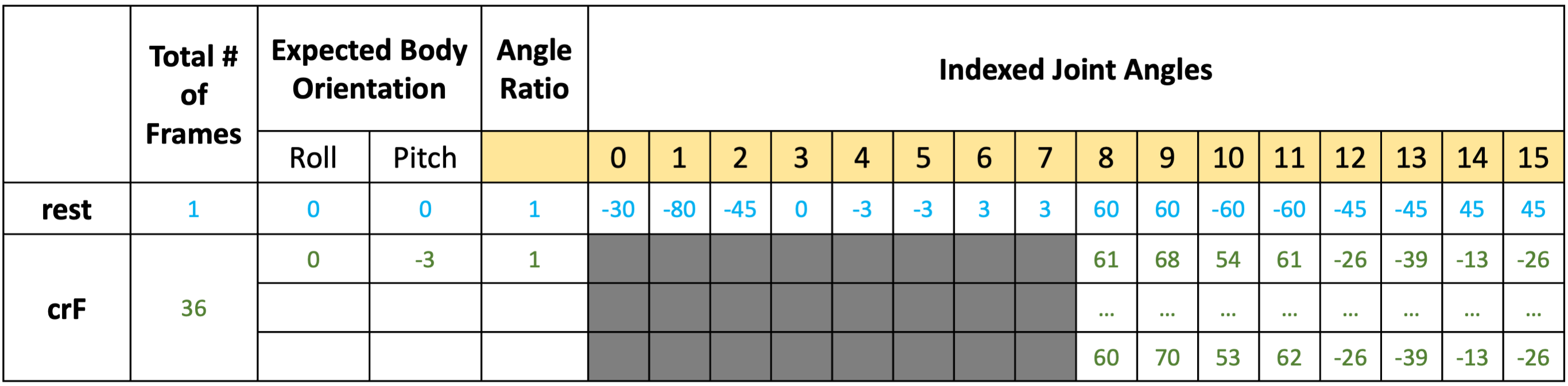
Fig. 11.2 Skill Definition
rest is a static posture, it has only one frame of 16 joint angles. crF is the abbreviation for “crawl forward”. It has 36 frames of 8 (or 12, depending on the number of walking DOF) joint angles that form a repetitive gait. Expected body orientation defines the body angle when the robot is conducting the skill. If the body is tilted from the expected angles, the balancing algorithm will calculate some adjustments. Angle ratio is used when you want to store angles larger than the range of -128 to 127. Change the ratio to 2 so that you can save those large angles by dividing 2.
Warning
A posture has only one frame, and a gait has more than one frames and will be looped over.
The following example is a behavior:
const char pu[] PROGMEM = {
-8, 0, -15, 1,
6, 7, 3,
0,    0,   0,   0,   0,   0,   0,   0,  30,  30,  30,  30,  30,  30,  30,  30,       5, 0, 0, 0,
15,   0,   0,   0,   0,   0,   0,   0,  30,  35,  40,  29,  50,  15,  15,  15,       5, 0, 0, 0,
30,   0,   0,   0,   0,   0,   0,   0,  27,  35,  40,  60,  50,  15,  20,  45,       5, 0, 0, 0,
15,   0,   0,   0,   0,   0,   0,   0,  45,  35,  40,  60,  25,  20,  20,  60,       5, 0, 0, 0,
0,    0,   0,   0,   0,   0,   0,   0,  50,  35,  75,  60,  20,  30,  20,  60,       6, 0, 0, 0,
-15,  0,   0,   0,   0,   0,   0,   0,  60,  60,  70,  70,  15,  15,  60,  60,       6, 0, 0, 0,
0,    0,   0,   0,   0,   0,   0,   0,  30,  30,  95,  95,  60,  60,  60,  60,       6, 1, 0, 0,
30,   0,   0,   0,   0,   0,   0,   0,  75,  70,  80,  80, -50, -50,  60,  60,       8, 0, 0, 0,
};
pu is short for “push up”, and is a “behavior”. Its data structure contains more information than posture and gait.
The first four elements are defined the same as before, except that the number of frames is saved as a negative value to indicate that it’s a behavior. The next three elements define the repeating frames in the sequence: starting frame, ending frame, looping cycles. So the 6, 7, 3 in the example means the behavior should loop from the 7th to the 8th frame for 3 times (the index starts from 0). The whole behavior array will be executed only once, rather than looping over like the gait.
Each frame contains 16 joint angles, and the last 4 elements define the speed of the transition, and the delay condition after each transition:
The default speed factor is 4, it can be changed to an integer from 1 (slow) to 127 (fast). The unit is degree per step. If it’s set to 0, the servo will rotate to the target angle by its maximal speed (about 0.07sec/60 degrees). It’s not recommended to use a value larger than 10 unless you understand the risks.
The default delay is 0. It can be set from 0 to 127, the unit is 50 ms.
The 3rd number is the trigger axis. If it’s not 0, the previous delay time will be ignored. The trigger of the next frame will depend on the body angle on the corresponding axis. 1 for the pitch axis, and 2 for the roll axis. The sign of the number defines the direction of the threshold, i.e. if the current angle is smaller or larger than the trigger angle.
The 4th number is the trigger angle. It can be -128 to 127 degrees.
11.2.3. Suffix for indicating Instinct and Newbility
You must upload WriteInstinct.ino to have the skills written to EEPROM for the first time. The following information will be used:
const char* skillNameWithType[] =
{"crI", "puI", "restI", "zeroN",};
const char* progmemPointer[] =
{cr, pu, rest, zero, };
Warning
Notice the suffix I or N in the skill name strings. They tell the program where to store skill data and when to assign their addresses.
Later, if the uploaded sketch is the main sketch OpenCat.ino, and if you are using NyBoard that has an I2C EEPROM, the program will only need the pointer to the Newbility list
const char* progmemPointer[] = {zero};
to extract the full knowledge of pre-defined skills.
11.3. Define new skills and behaviors
11.3.1. Modify the existing skill template
There’s already a skill called “zeroN” in InstinctBittle.h. It’s a posture at the zero state waiting for your new definition. You can first use the command mIndex Offset to move an individual joint to your target position, then replace the joint angles (bold fonts) in array at once:
const char zero[] PROGMEM = {
1, 0, 0, 1,
0,  0,  0,  0,  0,  0,  0,  0,  0,  0,  0,  0,  0,  0,  0,  0,};
Because it’s declared as a Newbility and doesn’t require writing to I2C EEPROM, you can simply upload OpenCat.ino every time you change the array (without uploading WriteInstinct.ino). You can trigger the new posture by pressing 7> on the IR remote, or type kzero in the serial monitor.
You can rename this skill, but remember to update the keymap of the IR remote.
11.3.2. Add more skills in InstinctBittle.h
You can add more skills in InstinctBittle.h. Remember to increase the skill number at the beginning of the file and add the corresponding skill name and pointer in the skill list array.
A skill can be called from the serial monitor with the token ‘k’ command. For example, ksit will move Bittle to posture “sit”.
You can also tune new skills by sending posture frames through the serial port, using the m, i, l tokens without uploading a new sketch. After fine-tuning the skill, you can save it in the instinctBittle.h and upload it to the board as a newbility or instinct.
Warning
Always check the actual code for the available skill names. We may alter the skill set as we iterate the software.
This git repo ( https://github.com/ger01d/kinematic-model-opencat ) is a good starting point if you want to develop a customized gait. If you are going to do some inverse kinematics calculation, you may use the following key dimensions to build your model.
11.3.3. Automation
So far Bittle is controlled by the infrared remote. You make decisions for Bittle’s behavior.
You can connect Bittle with your computer or smartphone, and let them send out instructions automatically. Bittle will try its best to follow those instructions.
By adding some sensors (like a touch sensor), or some communication modules (like a voice control module), you can bring new perception and decision abilities to Bittle. You can accumulate those automatic behaviors and eventually make Bittle live by itself!
Another direction is to set up a simulation for Bittle then test the model in reality. You may use this Unified Robot Description Format (URDF) ( https://github.com/AIWintermuteAI/Bittle_URDF ) file for Bittle to set up an NVIDIA Omniverse simulation.
11.4. Understand OpenCat.h
The controlling framework behind Bittle is OpenCat, which I’ve been developing for a while. You can learn more from posts available here ( https://www.hackster.io/petoi/opencat-845129 )
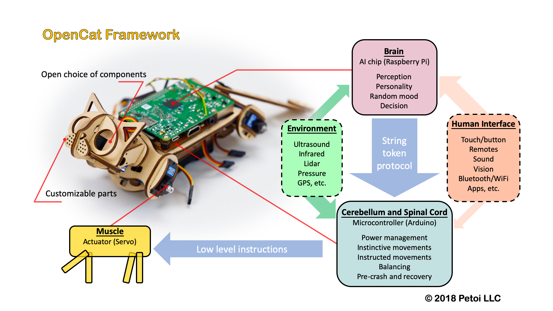
Fig. 11.3 Opencat Firmware Summary
Further reading abut code review: ( https://www.petoi.camp/forum/software/flavien-opencat-code-reviews )
11.5. Tutorial on Creating New Skills
11.5.1. Preparation
Get familiar with the standard process of assembly, uploading the standard program Opencat.ino, and calibration.
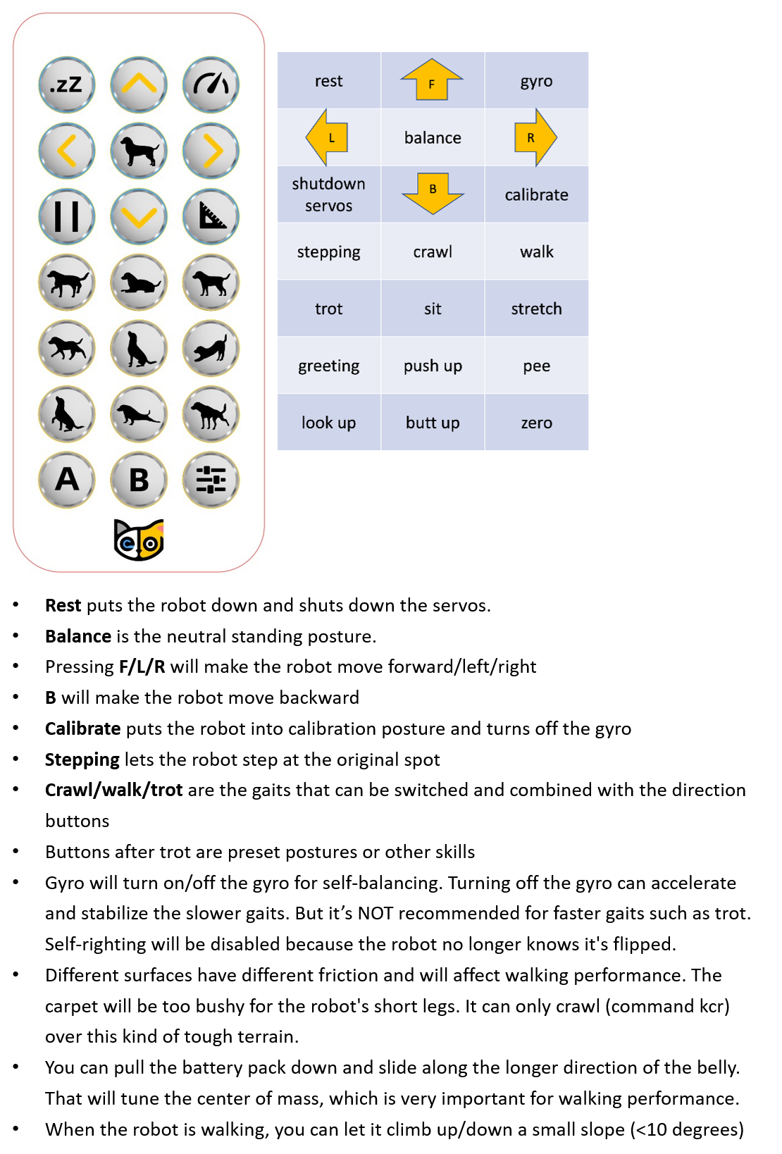
Fig. 11.4 IR Controls
Validate that the following functions work as expected.
Press the button which is in the 2nd row, the 2nd column on the IR remote. Later we will use (2, 2) as the index. You can also enter kbalance via serial port. Bittle should stand up and keep balance;
Press the button which is in the 7th row, the 3rd column on the IR remote. Later we will use (7, 3) as the index. You can also enter kzero via serial port. Bittle should enter a posture similar to the calibration state, which is the “zero” skill in the program (as shown in the figure below).
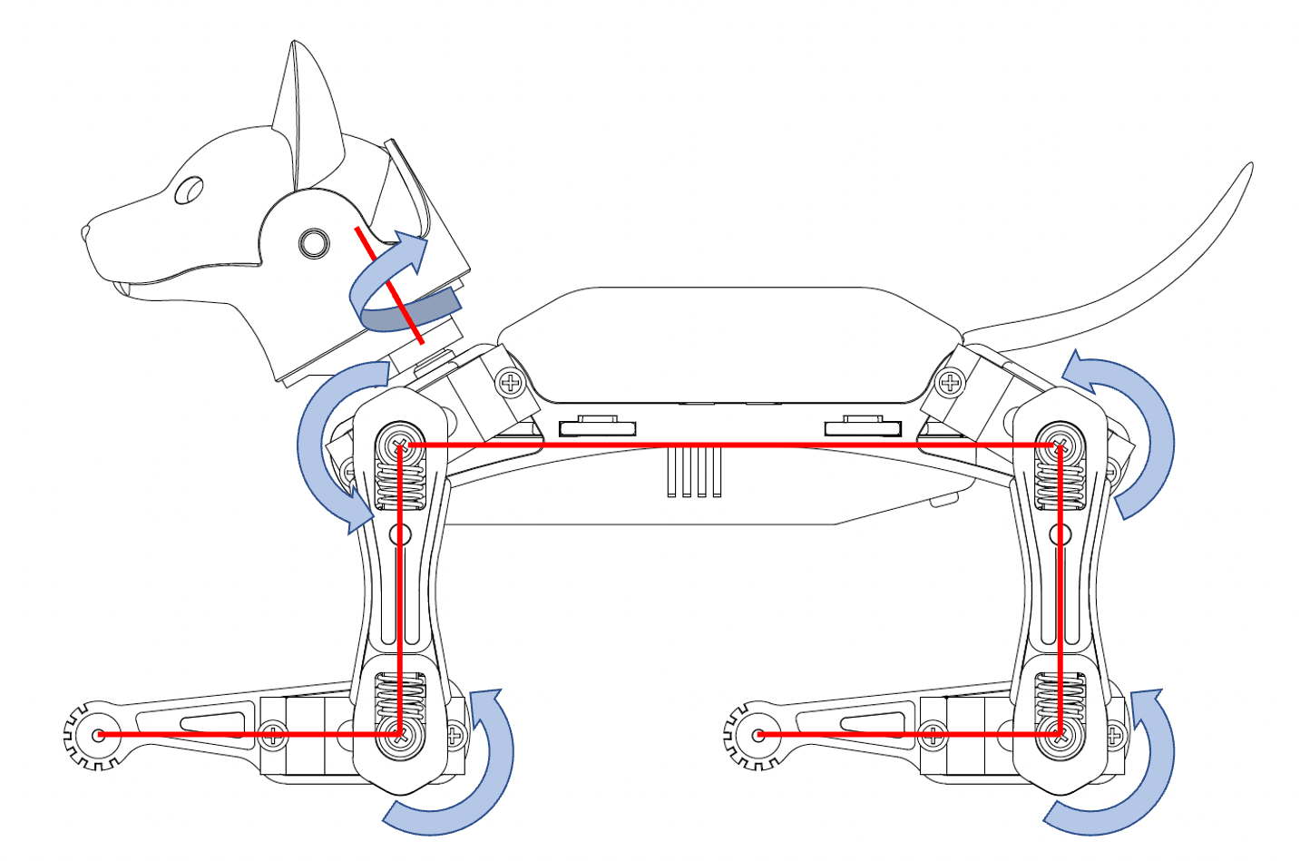
Fig. 11.5 Zero state of Bittle
Open the folder src/, create a backup file of instinctBittle.h as instinctBittle.hBAK.
The coordinate system of Bittle is shown in the figure below.
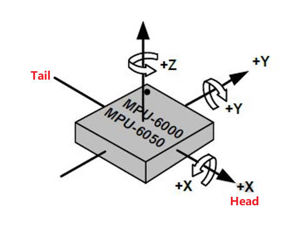
Fig. 11.6 IMU Direction
Yaw: Rotate around the Z-axis.
Pitch: Rotate around the Y-axis (nose up/down).
Roll: Rotate around the X-axis (tilt left/right).
For the legs, on the left side, counterclockwise is positive, clockwise is negative. On the right side, the rotation directions are mirrored. The origin position and rotation direction of a single leg (upper/lower leg) around the joint are shown in the 2nd figure.
The indexing order of all the joints is shown in the figure below:
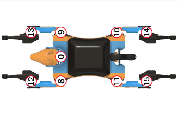
Fig. 11.7 Bittle top view with motor index
The skill arrays are defined in WriteInstinct/instinctBittle.h, formatted as the figure below. Note the index starts from 0.
Fig. 11.8 Skill Definition
Total # of Frames defines the number of frames of a certain skill.
For example, rest is a static posture, it has only one frame of 16 joint angles.
crF is the abbreviation for “crawl forward”. It has 36 frames of 8 (or 12, depending on the number of walking DOF) joint angles that form a repetitive gait.
Expected body orientation defines the body angle when the robot is conducting the skill. When all joints move to their corresponding joint angle values in the current frame, the body inclination should naturally reach the defined expected angle. If the body inclination deviates from the expected angle, the balance algorithm will calculate some adjustment values for each leg servo , in order to keep the body tilt as close to the expected angle as possible.
Angle ratio is used when you want to store angles larger than the range of -128 to 127. Change the ratio to 2 so that you can save those large angles by dividing 2.
11.5.2. Understand the format of a posture
Zero is a static posture, Find the zero array in instinctBittle.h:
const char zero[] PROGMEM = {
1, 0, 0, 1,
0,   0,   0,   0,   0,   0,   0,   0,   0,   0,   0,   0,   0,   0,   0,   0,};
Change some of these values to:
const char zero[] PROGMEM = {
1, 0, 0, 1,
70, 0, 0, 0, 0, 0, 0, 0, -60, 0, 0, 0, 60, 0, 0, 0,};

Fig. 11.9 Skill development Code Compare
Save the change, and upload the program OpenCat.ino to Bittle (Note: there is no need to upload writeinsict.ino or opencat.h), after upload, press the button (9) which is in the 7th row, the 3rd column on the IR remote to trigger the modified zero skill. You can see the posture is changed.
The new zero pose looks like this:
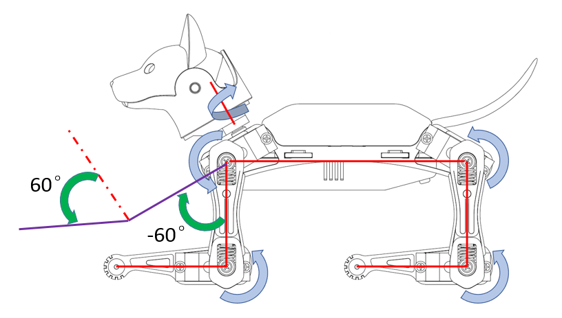
Fig. 11.10 Zero State with Angle
The first element (1) represents the total number of frames of the skill, 1 means it is a static posture.
The 4th element (1) represents the Angle ratio. It means all the following indexed joint angles are actual angles (because each of them multiply by 1).
From the 5th to the 20th elements represent 16 indexed joint angles.
For Bittle, the 5th element (joint index 0) means the servo on Bittle’s neck rotates counterclockwise 70 (the unit is in degrees). Bittle’s head turn to it’s left side.
The 13th element (joint index 8) means Bittle’s left upper leg rotates clockwise 60 (the unit is in degrees) around the joint.
The 17th element (joint index 12) means Bittle’s left lower leg rotates counterclockwise 60 (the unit is in degrees) around the joint.
All the other indexed joint angles remain 0 (the unit is in degrees).
You can define a new posture and upload it to the robot. Call the new posture with the IR remote or the serial monitor.
11.5.3. Explain expected body orientations
Look at the example of:
const char balance[] PROGMEM = {
1, 0, 0, 1,
0,   0,   0,   0,   0,   0,   0,   0,  30,  30,  30,  30,  30,  30,  30,  30,};
and
const char sit[] PROGMEM = {
1, 0, -30, 1,
0,   0, -45,   0,  -5,  -5,  20,  20,  45,  45, 105, 105,  45,  45, -45, -45,};

Fig. 11.11 Skill development Code Compare
The 2nd and 3rd elements represent Expected body orientation, corresponding to the roll angle and the pitch angle.
The unit is in degrees.
The sign of the number follows the right-handed spiral rule, look along the direction pointed by the axis arrow, clockwise is positive, counterclockwise is negative.
With the gyro activated, rotate Bittle, when the body is tilted from the expected angles, the balancing algorithm will calculate some adjustments to keep it in this posture.
11.5.4. Explain angle ratio
Look at the example of
const char rc[] PROGMEM = {
-3, 0, 0, 2,
0, 0, 0,
0,    0,   0,   0,   0,   0,   0,   0, -88, -43,  67,  87,  42, -35,  42,  42,      15, 0, 0, 0,
0,    0,   0,   0,   0,   0,   0,   0, -83, -88,  87,  42,  42,  42,  42, -40,      15, 0, 0, 0,
-8, -20, -11,   0,  -1,  -1,   0,   0,  18,  18,  18,  18, -14, -14, -14, -14,      10, 0, 0, 0,
};
Angle ratio is designed for large angles out of the range -128~127.
The 4th element (2) represents the angle ratio. It means all the following all indexed joint angles real values is equal to each of them multiply by the value of this angle ratio.
11.5.5. Understand the format of a gait
A series of frames defines sequential postures, such as a gait. Find the bk array in instinctBittle.h:
bk is the abbreviation for “back”.
The first four elements are defined the same as before, The first element (35) means it has 35 frames. Next are 35 frames of 8 indexed joint angles that form a repetitive gait.
11.5.6. Understand the format of a behavior
Modify the zero skill as:
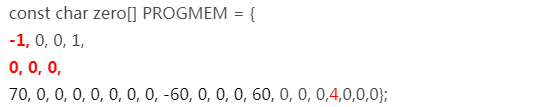
Fig. 11.12 Zero position
Upload the new zero skill and see the effect. It should be the same. (Later explanation a posture can be considered as a behavior or gait with one frame.)
Copy the content of hi array to zero:
Change a few values:
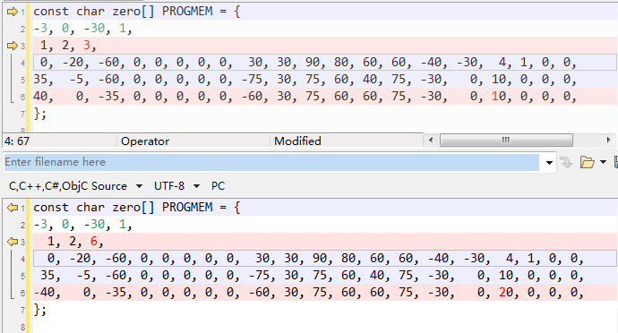
Fig. 11.13 Skill development Code Compare
Save and upload OpenCat.ino. Call the new zero skill to see the effect.
For example, the modified hi behavior:
The first four elements are defined the same as before, except that the number of frames is saved as a negative value (-3) to indicate that it’s a behavior.
The 2nd element (0) means the Roll rotation body angle is 0 (The unit is in degrees). The 3rd element (-30) means the Pitch rotation body angle is -30 (The unit is in degrees). If the body is tilted from the expected angles, the balancing algorithm will calculate some adjustments. The 4th element (1) means all the following all indexed joint angles are real values.
The next three elements define the repeating frames in the sequence: starting frame (1), ending frame (2), looping cycles (6). So the 1, 2, 6 in the example means the behavior should loop from the 2nd to the 3rd frame for 6 times (the index starts from 0). The whole behavior array will be executed only once, rather than looping over like the gait.
For behavior, each frame contains 16 indexed joint angles, and the last 4 elements define the speed of the transition, and the delay condition after each transition:
The first number represents speed factor. The default speed factor is 4, it can be changed to an integer from 1 (slow) to 127 (fast). The unit is in degrees per step. If it’s set to 0, the servo will rotate to the target angle by its maximal speed (about 0.07sec/60 degrees). It’s not recommended to use a value larger than 10 unless you understand the risks. Here for this example, in the first frame, it is default value (4).
The 2nd number represents delay time. The default delay is 0. It can be set from 0 to 127, the unit is 50 ms. Here for this example, in the first frame, it is 1.
The 3rd number represents the trigger axis. If it’s not 0, the previous delay time will be ignored. The trigger of the next frame will depend on the body angle on the corresponding axis. 1 for the pitch axis, and 2 for the roll axis. The sign of the number defines the direction in which the threshold is exceeded. In the first frame of this example, it is 0, which means this trigger condition is not enabled.
The 4th number represents the trigger angle. It can be -128 to 127 degrees. The use of this value needs to be combined with the third number. Only when the robot body rotates in the specified direction exceeds this trigger angle, the action of the next frame can be triggered. In the first frame of this example, it is 0. If the third number is 0, it means that the trigger condition is not enabled, and this value is invalid.
11.5.7. Understand the memory structure
Explanation the locations:
There are two kinds of skills: Instincts and Newbility. The addresses of both are written to the onboard EEPROM(1KB) as a lookup table, but the actual data is stored at different memory locations:
I2C EEPROM (8KB) stores Instincts.
The Instincts are already fine-tuned/fixed skills. You can compare them to “muscle memory”. After uploading the “parameters” firmware, multiple instinctive Instincts write linearly to the I2C EEPROM. Their addresses are generated during the upload of the “parameters” firmware and saved to a lookup table in the onboard EEPROM.
Flash (sharing the 32KB flash with the program) stores Newbility.
A Newbility is any new experimental skill that requires a lot of tests. It’s not written to the I2C nor onboard EEPROM, but the flash memory in the format of PROGMEM. It has to be uploaded as one part of the Main function firmware. Its address is also assigned during the runtime of the code, though the value rarely changes if the total number of skills (including all Instincts and Newbilities) is unchanged.
The implementation code:
The first section is active when uploading “parameters” firmware. It contains all the skills’ data and pointers. The skill names contain a suffix, “N” or “I” to indicate whether it’s a Newbility or Instinct. The Instinct will be saved to the external I2C EEPROM while the Newbility will be saved to the flash. The address of all the skills will be saved to the onboard EEPROM.
The second section is active when uploading Main function firmware. Because the Instincts are already saved in the external EEPROM, their data is omitted to save space. The Newbility will be saved to the flash with the upload so you can update them in the MAIN_SKETCH section . It’s very useful if you are still tuning a new skill.
In the example code, only zero is defined as a Newbility so you don’t need to re-upload “parameters” firmware for experiments.
11.5.8. Create a new behavior
What if we want to add more skills with customized names and button assignments?
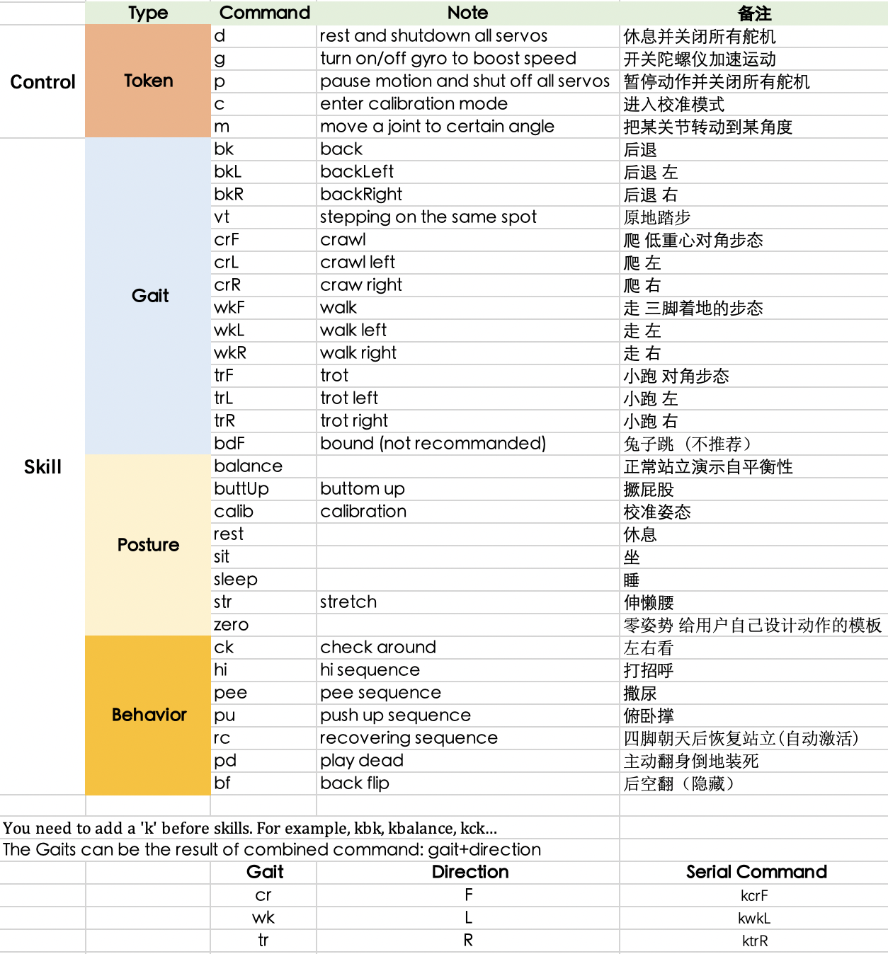
Fig. 11.14 Serial Commands
If you want to add more skills, you can refer to the implementation of serial commands (the figure above) and keymap (the 1st figure) in the program code.
Add an example of a Newbility test and assign it to a button on the IR remote. Upload the skill and call it with both IR remote and serial monitor.
Modify a few fields of test to make it an Instinct. Call the behavior with the IR remote or serial monitor.
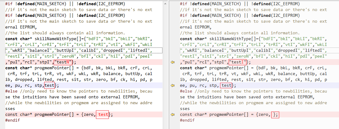
Fig. 11.15 Skill development Code Compare
Warning
Note: The left side of the above picture is to add a new skill (Newbility); the right side is to add a new instinct (Instinct).
Remember to add 1 to the number of skills at the beginning of the header file.
Then you can call this test by entering ktest in the serial monitor. You can also call it from the IR remote if you replace a button definition in OpenCat.h.
11.5.9. Tune skills in realtime
You need to understand the above structure to store a skill on the robot. However, when tuning the skills, things can be easier. To do this, you can connect your computer with the robot through the USB or Bluetooth connector. Then you can send string commands that define the joint angles. The program on the NyBoard will listen and perform the instructions in real-time. In the folder SerialMaster , you can find the ardSerial.py to play the role of Arduino IDE’s serial monitor, and you can also write scripts to control Bittle to do more complex movements. Some use cases are listed in example.py.
Please refer to Controlling with Python section for more details.